Week -2
- AIM 1: Make a Simulink model of Doorbell using solenoid block with the following details.
- OBJECT: When the switch is closed the electromagnet receives electrical power from the battery and pulls the metal arm to hit the bell producing sound. Create a situation where the switch is closed for 2 seconds and then released. Observe the physical movement of the plunger.
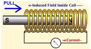
- Door Bell construction: Given-
Above diagram shows construction of a door bell using a solenoid which is a electromagnet.
Construction and working - A battery source provides power. The switch is turned on which allows the current to pass through the conducting wires, hence magnetic field is generated around it which attracts magnetic materials results exciting the electromagnet and the plunger is attracted by pulling it towards the metal portion which results to produce sound. This phenomenon is used as a doorbell.
Solenoid:
- Simullink Block Diagram:
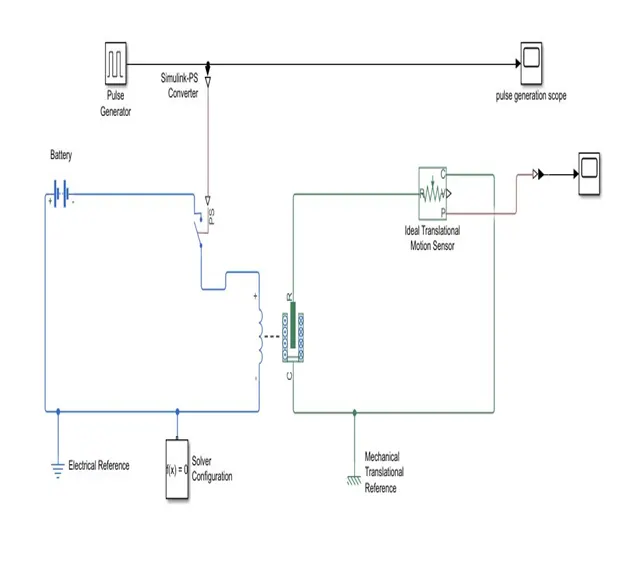
- Simulink Blocks Used:
- Pulse Generator: This block generates square wave pulses at regular intervals of time. The waveform parameters, Amplitude, Pulse Width, Period, and Phase delay, determine the shape of the output waveform.
- Simulink PS converter: This block is used to convert Simulink input signal into physical signal.
- Battery Source: This block is used to power the electrical circuit.
- Switch: This block is used as circuit breaker.
- Electrical Reference: This block is used as grounding componentby connecting to the circuit represents a reference point for all Electrical translation ports.
- Solver Configuration: This block specifies the solver parameters that model needs before a simulation operation.
- Ideal Translational Motion Sensor: This block is used to convert a variable measured between two mechanical translational nodes into a control signal proportional to velocity or position.
- Mechanical Reference: This block is used as grounding componentby connecting to the circuit represents a reference point for all Mechanical translation ports.
- Solenoid: This block is a device consists of a coil of wire and a movable plunger as armature which is attracted by pulling it towards the metal portion by magnetic field generated around the coil. It converts Electrical Energy to Mechanical Energy.
- Scope: This block shows plot of the signals generated during simulation.
- Results and Observations:
The Plot 1 shows the input signals of the pulse generator which shows for the interval of every two seconds is on and repeats the cycle for 20 seconds.
The Plot 2 shows the output signals from the Ideal Translational Motion Sensor, where by solenoid block the behavior of the plunger arrangement is when at value of X is 5mm plunger is away from C while at X is 0mm the plunger is near to C.
Also spikes in the Graph are due to the Electromagnetic interferences.
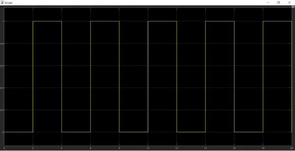
Plot 1
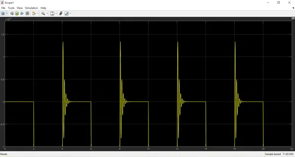
Plot 2
- Aim 2: Make a Simulink model to use a thermistor to sense the temperature of a heater & turn on or turn off the fan.
- Object: Temperature source: 20 °C from 0 to 10 seconds, 27 °C from 10 to 30 seconds, 23 °C from 30 to 50 seconds Fan conditions: ON if the temperature above 25 °C, OFF otherwise.
- Simulink Block Diagram:
- Simulink Blocks used:
Signal Builder- This block is used to generate the signal according to the input conditions.
PS-Simulink Converter- This block is used to convert Simulink signals to the respective physical signal.
Controlled Temperature Source- This block represents an ideal energy source in a thermal network that can maintain a controlled temperature difference regardless of the heat flow rate. The temperature difference is set by the physical signal port S. A positive temperature difference causes the temperature at port B to be greater than the temperature at port A.
Thermal Reference: This block is used as a reference point in a thermal network where the temperature is equal to absolute zero.
Solver configuration: This block is used as a solver setting to use for simulation.
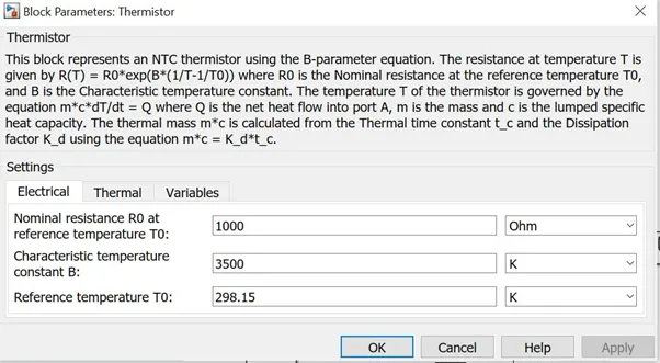
Thermistor: This block represents an NTC thermistor using the B-parameter equation. The resistance at temperature T is given by R(T) = R0*exp(B*(1/T-1/T0)) where R0 is the Nominal resistance at the reference temperature T0, and B is the Characteristic temperature constant. The temperature T of the thermistor is governed by the equation m*c*dT/dt = Q where Q is the net heat flow into port A, m is the mass and c is the lumped specific heat capacity. The thermal mass m*c is calculated from the Thermal time constant t_c and the Dissipation factor K d using the equation m*c = dT/dt=Q
Battery: This block provides the supply source to the circuit.
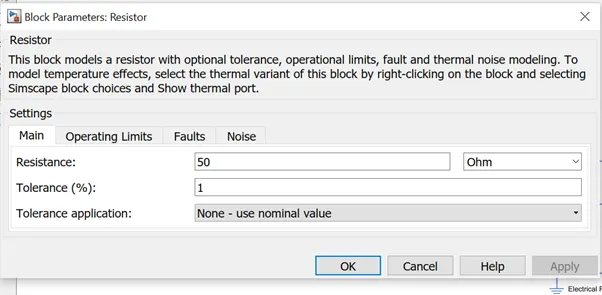
Resistor: This block demonstrates the voltage-current (V-I) relationship for a linear resistor is V=I*R, where R is the constant resistance in ohms. The positive and negative terminals of the resistor are denoted by the + and - signs respectively. By convention, the voltage across the resistor is given by V(+)-V(-), and the sign of the current is positive when flowing through the device from the positive to the negative terminal. This convention ensures that the power absorbed by a resistor is always positive.
Electrical Reference: This block is used as a reference point in a thermal network where the temperature is equal to absolute zero.
Voltage Sensor: This block is used as an ideal voltage sensor, that is, a device that converts voltage measured between any electrical connections into a physical signal proportional to the voltage.
Display: This block is used as a representing block for the given input or output signals.
P-S Simulink converter: This block is used to convert physical signal to the respective Simulink signals.
Constant: This block provides constant output values.
Switch: This block is used as a circuit breaker defines as the passage through input 1 when input 2 satisfies the selected criterion; otherwise, pass through input 3. The inputs are numbered top to bottom (or left to right). The first and third input ports are data ports, and the second input port is the control port. The criteria for control port 2 are u2 >= Threshold, u2 > Threshold or u2 ~= 0.
Scope: This block shows plot of the signals generated during simulation.
Model Explanation:
- Signal Builder
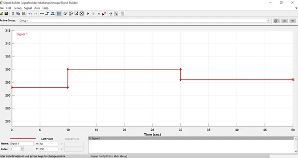
As per the given conditions, signal is build as
Temperature source:
20 °C (293 K) from 0 to 10 seconds,
27 °C (300 K) from 10 to 30 seconds,
23 °C (296 K) from 30 to 50 seconds.
Thermistor inputs:
Values of reference temperature is set to 298.15K and the Beginning value is set to 293K.
Resistor:
Value of resistance selected is 50 ohm with 1% Tollerance
.
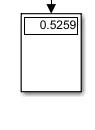
Voltage sensor: To obtain the Threshold voltage voltage sensor is connected in the Simulink model which displays the result in Display Block as (0.5259)
Switch :
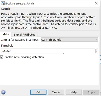
The threshold of the Switch is set to 0.5259 such that as the requirement of the fan is to work and turned on only when the temperature is greater than 25degree Celcius or (298 K).
Also the threshold voltage is 0.5259 for the temperature 25 degree Celcius.
The configuration of the switch are in the way that if the value is below the threshold value the switch is open. And the switch is closed if the valuer of the voltage gets increased than the threshold voltage.
Results and Obseervations :
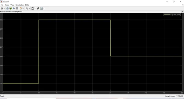
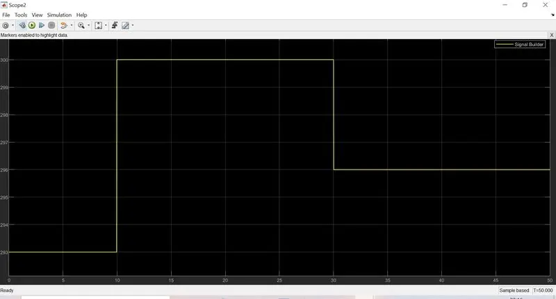
- The Scope Showing the plotted results Temperature vs Time of Signal Builder.
Plot 1
20 °C (293 K)from 0 to 10 seconds,
27 °C(300 K) from 10 to 30 seconds,
23 °C (296 K) from 30 to 50 seconds.
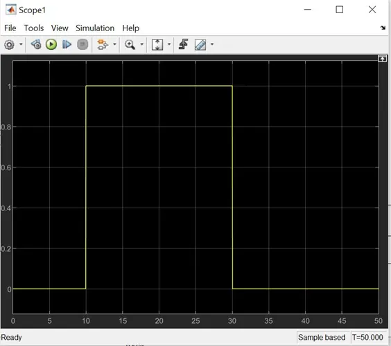
- It is observed through the plot in the scope1 that the switch is closed for the time ranging from 10 to 30 seconds. It can be predicted that the fan will not turn on time ranging 0 to 10 seconds and 30 to 50 seconds.
Plot 2
References: MATLAB HELP
Submitted By : Rahul Koli
Date: 04/09/2021