EV Drivetrain
EV DRIVE TRAIN
- Which types of power converter circuits are employed in electric and hybrid electric vehicle?
A power converter is an electrical circuit that changes the electric energy from one form into the desired form optimized for the specific load. A converter may do one or more functions and give an output that differs from the input. It is used to increase or decrease the magnitude of the input voltage, invert polarity, or produce several output voltages of either the same polarity with the input, different polarity, or mixed polarities such as in the system (computer) power supply unit. The converter acts as the link or the transforming stage between the power source and the power supply output. There are several kings of converters based on the source input voltage and the output voltage and these falls into four categories namely:
- The AC to DC converter known as the rectifier,
- The AC to AC converter or frequency changer,
- The DC to DC voltage or current converter, and
- The DC to AC inverter.
The converter uses non-linear components such as the semiconductor switches, and linear reactive components such as the inductors, transformers and capacitors for intermediate energy storage as well as current and voltage filtering. The size, weight and cost of the converter are largely determined by these components. As we know, the EV or HEV requires at least one source conversion in the form of DC hence we do not use AC to AC converters in these vehicles. The other three types of converters are used in different parts of the hybrid or electric vehicle.
AC to DC Converters
A type of converter that changes input AC signal into a DC is known as AC to DC converter or rectifiers. The rectifier converts the AC supply into the DC supply at the load end connection. Similarly, transformers are normally used to adjust the AC source to reduce the voltage level to have a better operation range for DC supply. They also find common application in renewable energy management, test & measuring equipment, defence, aerospace, and transportation systems.

AC to DC Converter is further classified as:
Diode Rectifiers: This rectifier circuit changes applied ac input voltage into a fixed dc voltage. Either a single-phase or three-phase ac signal is applied at the input.
Application: These are mainly used in electric traction and in electrochemical processes like electroplating along with in battery charging and power supply. These are also used in welding and UPS related services.
Phase Controlled Rectifiers: Unlike diode rectifiers, phase-controlled rectifiers are designed to convert a fixed value of ac signal voltage into a variable dc voltage. Here line voltage operates the rectifier hence these are sometimes known as line commutated ac to dc converters. Similar to diode rectifiers, here also the applied ac signal can be a single-phase or three-phase ac signal.
Applications: DC drives, HVDC systems, compensators, metallurgical and chemical industries as well as in excitation systems for synchronous machines.
DC to DC Converters
The converters that convert the dc signal of fixed frequency present at the input into a variable dc signal at the output are also known as choppers. Here the achieved output dc voltage may have a different amplitude than the source voltage. Generally, power transistors, MOSFETs, and thyristors are the semiconductor devices used for their fabrication. The output is controlled by a low power signal that controls these semiconductor devices from a control unit.

Here forced commutation is required to turn off the semiconductor device. Generally, in low power circuits power transistors are used while in high power circuits thyristors are used.
Choppers are classified on the basis of the type of commutation applied to them and on the basis of the direction of power flow. Some major uses of choppers are in dc drives, SMPS, subway cars, electric traction, trolley trucks, vehicles powered by battery, etc. However, the chopper topologies can be made bi-directional, in which the power flow can be in either direction which is useful in regenerative braking of electric of hybrid electric vehicles.
DC to AC Converters
The devices that are designed to convert the dc signal into ac signal are known as inverters. The applied input is a fixed dc voltage that can be obtained from batteries but the output obtained is variable ac voltage. The voltage and frequency of the signal obtained are of variable nature. Here the semiconductor device i.e., the thyristor is turned off by using either line, load, or forced commutation.
Thus, it can be said that by the use of inverters, a fixed dc voltage is changed into an ac voltage of variable frequency. Generally, the semiconductor devices used for its fabrication are power transistors, MOSFETs, IGBT, GTO, thyristors, etc.

Inverters mainly find applications in induction motor and synchronous motor drives along with UPS, aircraft, and space power supplies.
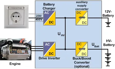
Like choppers, in inverters also conventional thyristors are used in high power applications and power transistors are used in low power applications. The inverter functions to change the direct current (DC) on the battery into an alternating current (AC) and then this alternating current is used by an electric motor. Or in other words, the rate at which the voltage cycles from positive to negative and back again can be changed dramatically.
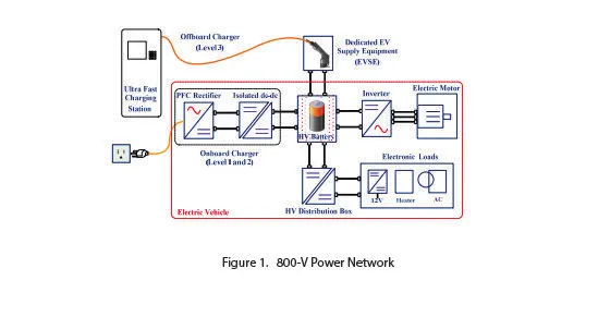
This is what’s needed to control the rotation speed of the motor. In addition, the inverter on an electric car also has a function to change the AC current when regenerative braking to DC current and then used to recharge the battery. The type of inverter used in some electric car models is the bi-directional inverter category.
2. An Electric Vehicle's powertrain with 72V battery pack in shown in the diagram below. The duty ratio for acceleration operation is 'd1' and for the braking operation the duty ratio is 'd2'.
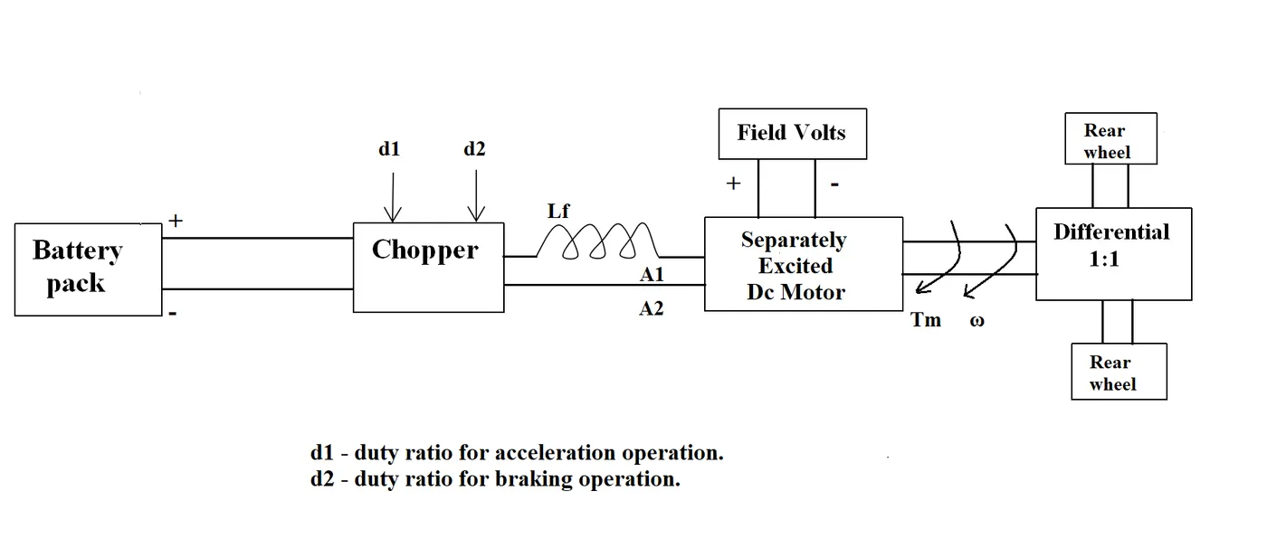
The other parameters of the electric vehicle is given below,
Motor and Controller Parameters:
Rated Armature voltage= 72 V
Rated armature current= 400 A
Ra= 0.5Ω, KΦ= 0.7 Volt second
Chopper Switching frequency= 400 Hz
The vehicle speed-torque characteristics are given by the below equation

What is EV steady state speed if duty cycle is 70%?
Given:
Rated Armature voltage, Va = 72 V
Rated armature current, Ia = 400 A
Ra= 0.5Ω,
KΦ = 0.7 Volt second
Chopper Switching frequency, Fc = 400 Hz
Vehicle Torque, Tv = 24.7 + (0.0051)w^2
To find: Steady state vehicle (ω) with duty cycle, D = 70%
W.k.t, T = V/Ra (KΦ) – ω/Ra (KΦ)2
Since the vehicle torque equation is given and it is asked to find the steady state speed of the vehicle we need to find the output voltage of the vehicle at which it runs. The output voltage of the vehicle is the product of the battery voltage or the source voltage available in the vehicle and the duty cycle of the vehicle.
Vo = Va*D
As, we need to find the vehicle speed at 70% of the duty cycle D = 0.70 will be used.
Vo = 72*0.7 = 50.4V
Now that we have got the vehicle voltage, we can find torque using the formulae given above. Here V = Vo since we do not use the battery voltage directly in the vehicle so the vehicle output voltage is used in the place of V
T = Vo/Ra (KΦ) – ω/Ra (KΦ)2
T = 50.4/0.5 (0.7) – ω/0.5 (0.7)2 = 70.56 – 0.98 ω
T = 70.56 – 0.98 ω
We already have the vehicle torque equation give, so compare T and Tv.
T = Tv
70.56 – 0.98 ω = 24.7 + (0.0051)w^2,
on simplifying this forms a quadratic equation,
0.0051 ω2 + 0.98 ω – 45.86
w.k.t, on solving using the quadratic formulae we get two values for ω as 38.9117 rad/sec and -231.069 rad/sec. The negative sign indicates the reverse direction. Since the motor and vehicle moves in forward direction we can ignore that value.
ω = 38.9117 rad/sec
Therefore, the steady state speed of an electric vehicle with 70% duty cycle is 38.9117 rad/sec.
- Develop a mathematical model of a DC Motor for the below equation using Simulink.
ω = (V/Kϕ) - (Ra/Kϕ) ^2 .T
From observing the equation given, we know it is the formula for finding the steady state speed of the EV. Hence the output Simulink model for this equation gives the graphical and figure value of speed of the EV.
Mathematical model of DC motor speed-torque characteristics is shown below:
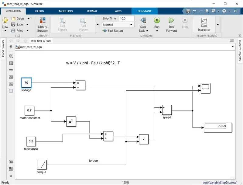
Blocks used:
Constant block – voltage, motor constant, armature resistance.
Multiplication-division block, product block, math operation (for power) block to square the motor constant and adder block to calculate the speed.
Ramp block - torque input, scope and display.
The connections are made as shown in the figure shown above. The supply voltage is taken as 70 voltage, motor constant and the armature resistance are assumed as 0.7 volt-second and 0.5 ohms. Since the torque is taken as a ramp signal it increases linearly, proportional to the simulation time.
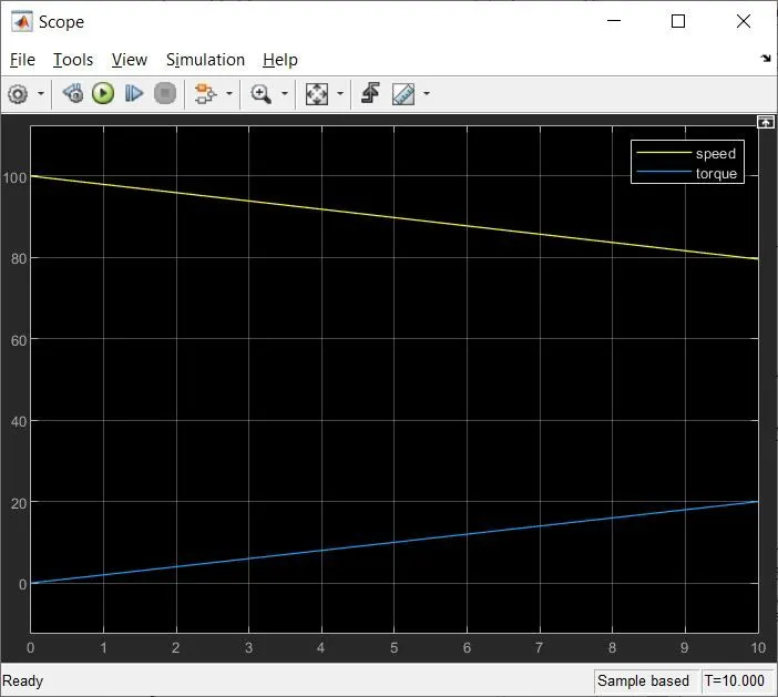
From the graph it is verified that at 10 Nm torque the speed is approximately 80 rad / sec. We can also see that for every value of the torque increasing from 0, the speed decreases and are linear in nature. Hence we can conclude that the torque and speed characteristics of the DC motor is inversely proportional.
- Refer to the blog on topic: Induction Versus DC brushless motors by Wally Rippel, Tesla.
Explain in brief about author’s perspective.
Wally Ripple who has passion for Electric vehicle since his undergraduate days had become the proponent of EV in Tesla motors, who also was an engineer in GM for EV1. He worked on research projects who tried to address us about the types of motors used in EV and their purpose along with their pros and cons. At the beginning itself he mentioned that one size does not fit all, which clearly depicts the comparison of two motors and how it can be used efficiently. The author tries to draw a outer view of the selection of motor based on the requirement, performance, environmental and other deciding factors.
Through out the blog he has walked us through the two types of motors: DC brushless and induction motor (3-phase). The comparison and examples given in the blog is sequentially explained in brief. At first, he tries to give us an idea about the machine appearances by pointing out the physical difference that can be observed in both the machines are rotor and controllers. (The difference is the construction of rotor).
DC BRUSHLESS MOTOR:
The rotor produces magnetic field passing through stator core produce torque by interacting with currents in the windings. The torque remains constant and the conversion of electrical to mechanical energy is optimally efficient.
- These machines have no starting torque with fixed frequency supply and hence inverters are a must.
- Rotor cooling is easier as less heat is generated and peak point efficiency is generally higher for this drive.
- The eddy current and the hysteresis losses are minimized by adjusting the field strength. Also with the adjustment of B the copper losses reduces optimizing the efficiency.
- Can be operated at UPF loads and easier to control than induction motor (since IM has complex motor equations compared to DC).
- DC motors require position sensor whereas Induction motors need speed sensor.
- Not to mention the big sized motors due to expensive PM (permanent magnets) adds disadvantage to this motor.
INDUCTION MOTOR:
- Unlike DC brushless, these motors give their best performance at .85pf loads only.
- The main advantage of IM, can be directly connected to conventional utility. But this motor does not operate with DC and hence AC supply is a must.
- They have limitations to maximum starting speed and torque. Compared to DC machines the torque performance of IM’s are quite low.
- Field control is easier than DC as they have no permanent magnets attached. The voltage can also be adjusted depending on the loading condition and hence the efficiency of the machine is improved.
- Magnetic and conduction losses can be traded such that efficiency is optimized. This advantage becomes increasingly important as performance is increased.
- But it is actually difficult to control and achieve stability over entire torque-speed range and over temperature is more difficult with induction than with DC brushless. This means added development costs, but likely little or no recurring costs.
- Unlike DC motors, when the size increases the losses does not increase proportionally and hence it is preferred for high performance loads. The over all average efficiency of the motor is better.
Coming close to the conclusion the author points of the highlight of both machines: “DC brushless drives will likely continue to dominate in the hybrid and coming plug-in hybrid markets, and that induction drives will likely maintain dominance for the high-performance pure electrics.” For high torque BLDC motors and for constant speed Induction motors are preferable choices. He concludes by suggesting that both drives could work side by side for high performances in near future, as the hardware is common in both cases.
The link for matlab model is attached here:
https://drive.google.com/file/d/1-TEn14O6NG3nQS5Be5EQKElQ5n83QweA/view?usp=sharing