Mathematical Model of a DC Motor using Simulink & solving Steady State Speed based on the Duty Cycles (acceleration & deceleration) of the Motor
OBJECTIVES:
- To answer the question: Which types of power converter circuits are employed in electric and hybrid electric vehicle?
- To solve the following problem:
An Electric Vehicle's powertrain with 72V battery pack in shown in the diagram below. The duty ratio for acceleration operation is 'd1' and for the braking operation the duty ratio is 'd2'.
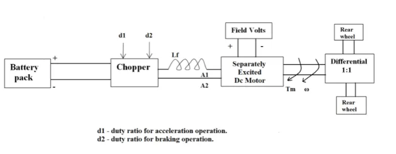
The other parameters of the electric vehicle is given below,
Motor and Controller Parameters:
- Rated Armature voltage= 72 V
- Rated armature current= 400 A
- Ra= 0.5Ω, KΦ= 0.7 Volt second.
- Chopper Switching frequency= 400 Hz
The vehicle speed-torque characteristics are given by the below equation:
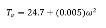
What is EV steady state speed if duty cycle is 70%?
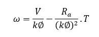
- To develop a mathematical model of a DC Motor for the below equation using Simulink:
- To answer the following question:
Refer to the blog on below topic:
https://www.tesla.com/blog/induction-versus-dc-brushless-motors
Induction Versus DC brushless motors by Wally Rippel, Tesla
Explain in brief about author’s perspective.
SOLUTIONS:
Solution to Objective 1:
Power electronic converters are used to convert voltages of a given magnitude and frequency to voltages of virtually any magnitude and frequency. One of the major functions of power electronics, therefore, is to provide the electrical power conversion which can achieve maximum functionality from electromechanical devices, energy sources, and electric loads. A second factor driving power electronics is efficiency. Efficient power conversion typically results in reduced material, cooling, power demand, cost, and volume while increasing reliability for many electronic products such as laptop computers and smartphones.
Power electronic converters enable electrical power conversion by periodically switching an available power source in and out of a circuit. These converters use semiconductor devices to act as switches, and feature energy storage devices, such as inductors and capacitors, to store energy and filter the sharp-edged waveforms created by the fast switchings. Transformers are used for isolation and safety in addition to voltage and current conversions.
Due to highly efficient power conversion capabilities of Power Converters, they are used in Electric Vehicles (EVs) and Hybrid Electric Vehicles (HEVs) to convert the major portion of power emanating from the power source into the required form. Power converters are able to convert a power signal in the form of its magnitude as well as its waveform.
The Power converters used in EVs and HEVs are as follows:
DC-DC Converter: These power electronics circuit converts a DC Voltage to a different DC Voltage. For example, the voltage of a fuel cell can drop significantly with increased power demand and a DC-DC converter is used to step up the fuel cell voltage to a higher level for a more efficient powertrain.
DC-AC Inverter: These power electronics circuit converts DC Voltage/Current to AC Voltage/Current. These days, the electric traction motor requires AC Voltage to operate rather than DC Voltage from the Battery. Hence a DC-AC inverter is required.
AC-DC Rectifier: These power electronics circuit converts AC Voltage/Current to DC Voltage/Current. An AC-DC Rectifier forms an integral part of charging infrastructure for EVs and HEVs. The electrical charging grid provides Alternating currents (AC) voltages and currents at a given frequency (Voltages and frequencies vary around the globe but in general, the AC supply frequencies is typically 50 Hz or 60Hz). The battery requires direct current (Direct Current) electricity, so the 1st stage of power conversion is to rectify and filter the AC waveform from the grid to DC.
Solution to Objective 2:
According to the question, the speed-torque characteristics for the motor is given by:
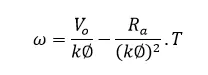
Where Vo is the output voltage.
Duty Cycle is mentioned to be 70% or 0.7.
The relation between the input armature voltage and the output voltage in the DC motor is given by:
Vo=d*Va
Where Va= input voltage or the armature voltage
D=duty cycle
Substituting the values of the motor parameters in the above equation:
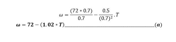
The above equation represents the speed-torque characteristics of the DC motor being used.
According to the question, the speed-torque characteristics for the vehicle is given by:

At steady state, the motor torque becomes equal to the vehicle torque and the vehicle rotational speed becomes equal to the DC motor rotational speed.
Therefore substituting the value of Tv of equation (b) in place of ‘T’ in equation (a):

Solving for ω in the above equation, the final value of ω:
(0.0051*ω2 ) + ω – 46.806 = 0
The values obtained on applying Sridharachariya’s formula to calculate the value of ω from the above equation are as follows:
ω=39.0294 rad/s and ω= - 235.107 rad/s
Since the vehicle is moving in the forward direction, the only possible value of ω is 39.024 rad/s
ω=39.024 rad/s (Answer)
Solution to Objective 3:
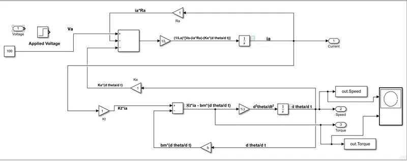
There are 2 primary equations required for mathematical modelling of a DC Motor:

where θ=angle turned by the rotor of the motor in radians
Jm = Moment of inertia of the DC motor
kt = Torque constant
ke = Back-emf constant
ia = Armature current
Ra = Armature resistance
Vin = Input Voltage
bm = Damping factor
These equations have been used to model a DC motor in Simulink:
My mathematical DC Motor model in Simulink:
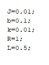
Parameters of the DC Motor assigned:
Plots obtained for a given 100V input:
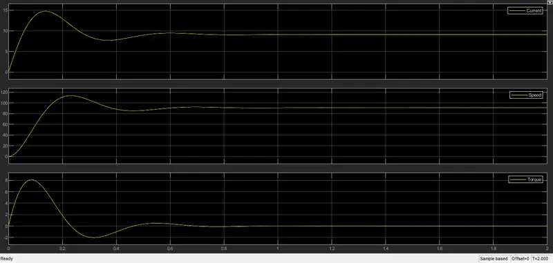
Plots obtained for 100 V input for Current, Speed, Torque w.r.t. Time
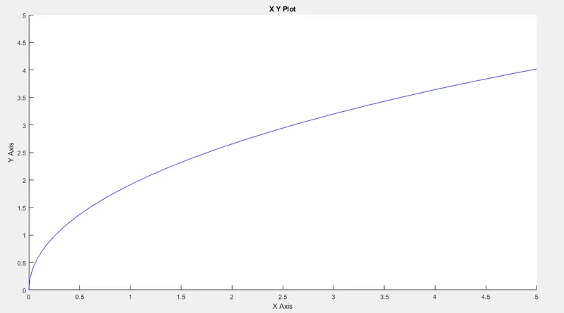
Output Torque-Speed Characteristics for the DC Motor for 100 V input
(x-axis -> Speed of rotor ; y-axis -> Torque generated)
Solution to Objective 4:
In the blog, Mr. Wally Ripel expels the notion that there is something called as a perfect engine for automobiles. In reality there is no perfect engine as that would have ended all the choices for engines and thereafter only the perfect engine would have remained in production. Instead of a perfect engine, there are different types of engines to suit personal requirements like price and performance.
Mr. Wally also explains through his personal experience that how Electric Vehicles have evolved over the years. The material for Battery has been replaced from Lead to Lithium, the DC Brushless Motor has been replaced by DC Brushless or Induction Motor. Similarly Contactors have given way to Modulating Inverters. In the future we may again see the current crop of components in the Electric Vehicles being replaced by components which cut down the production and running costs and at the same time improves performance and has a positive impact on the environment.
Mr. Wally further goes on to compare the Brushless DC Motors and the Induction Motors.
According to Mr. Wally, the DC Brushless Motor generates a torque interaction between the rotor and stator of the DC Motor when magnetic field lines, generated by 2 or more permanent magnets from the rotor enter the stator and interact with current carrying windings.
In order to maintain the constant torque output and efficient energy conversion (from electrical to mechanical), it is to be ensured that the magnitude and polarity of the stator be continuously varied and in the right way.
Explaining the Induction motor, Mr. Wally explains that the only difference between the Induction Motor and the Brushless Induction motor lies only in the rotor part of the Motor. The Stator part of both the motors are the same.
Unlike the Brushed DC Motor, the rotor of Induction Motor has no permanent magnets. Instead there are stacked steel laminations with buried peripheral conductors that form a “shorted Structure”. The current flowing in the stator windings produce a rotating magnetic field which interacts with this “shorted structure” in the rotor thus inducing a voltage which is proportionate to the difference between the applied frequency voltage and the rotational frequency of the rotor itself. Due to these induced voltage, currents are also produced within the rotor conductors which then again interacts with the original magnetic field to produce the required torque.
Unlike the brushless DC Motor which needs an inverter to generate the initial torque, there is a starting torque produced at the outset of a 3-phase induction motor. These very fact makes the invention of Induction motor by Nikola Tesla unique. The main success of Induction Motor lies in the fact that it is directly compatible with the conventional power utility. The Induction motor can run only on AC supply.
Although Induction Motors have certain limitations, still they are favoured over Brushless DC Motors due to overall efficiency in energy conversion and in applications where we need the speed of the DC motor to be constant. However, when efficiency of the motor can be ignored and top notch performances is the primary requirement, the brushless DC Motor is preferred as the torque generated is very high compared to Induction Motors.
DC Brushless motors were a popular choice for HEVs in the 1990’s with the exception of GM EV1 and the Tesla Roadster which housed Induction Motors.
There are multiple factors to be taken into consideration to decide whether Induction Motor is suitable for the vehicle or the DC Brushless Motor. Taking into considerations the sensors needed, the Brushless DC Motors requires only an absolute position sensor while an Induction Motor requires Speed Sensors. Another factor to be taken into consideration is the cost of permanent magnets required for installing in Brushless DC motors as it tends to be quite costly. The permanent induction motor needs good maintenance and needs skilled technicians to handle. Therefore the cost of induction motor is less.
Although, in general, the losses in a machine increases as it’s size increases, but in case of Induction this often does not hold true.
The writer concludes by saying that according to him, induction motor drives is better suited for high performance EV while DC Brushless Motor Drives is better suited for Hybrid as well as Plug-in Hybrid Electric Vehicles.
REFERENCES:
- https://skill-lync.com/premium/coursevideos/57200/en/6637
- Electric powertrain energy systems, power electronics drives for hybrid, electric fuel cell vehicles by Goodarzi, John G Hayes