Doorbell Modelling using Solenoid Block in Simulink and controlling Operation of a Heater Fan using Thermistor
AIM:
- To make a Simulink model of a Doorbell using Solenoid Block present in the Simulink Library and analyse the physical movement of the plunger(part of the Solenoid Block) on the basis of the following condition:
- The switch (essential element of the Doorbell circuit) is closed for 2 seconds and then released.
- To use a Thermistor to sense the temperature of a heater and turn off/on the fan as per the following conditions:
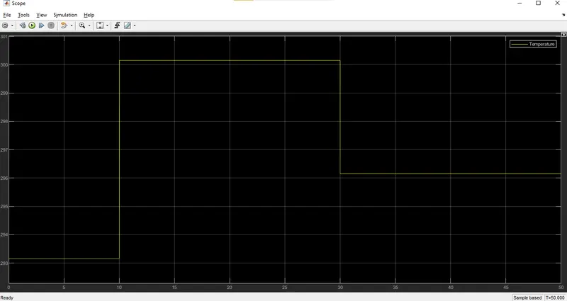
- Temperature source: 20°C for time period=0 to 10 seconds.
- Temperature source: 27°C for time period=10 to 30 seconds.
- Temperature source: 23°C for time period=30 to 50 seconds.
GOVERNING EQUATIONS & RELEVANT THEORY:
Doorbell:
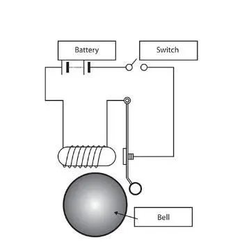
- The electric doorbell is a simple circuit that triggers a sound on pressing of a button.
- The pressing of a button corresponds to switching the circuit on.
- The circuit consists of a battery unit, a switch and a solenoid.
- The solenoid to be used in my project:
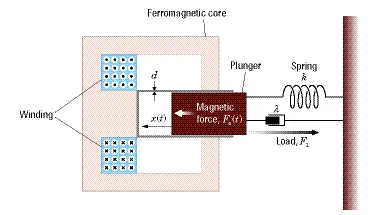
- The solenoid is basically an electromagnet (type of magnet in which a magnetic field is produced with the help of electric current). In this electromagnet, a coiled wire surrounds a metal piston. The piston contains a magnetically conductive material, so it can be moved back and forth due to electromagnetic field.
- In many instances, the solenoid piston consists of an iron core mounted to a non-magnetic metal bar. When there is no power to the electromagnet, there is no magnetic field production and a spring pushes the piston to the left, and the iron core extends outside of the wire coil. When you turn the electromagnet on (by pressing the doorbell button), there is magnetic field production, the piston pushes the spring and the piston gets compressed and the iron core is drawn to the magnetic field, so it slides into the centre of the coiled wire.
- As the iron core slides to the right, the end of the piston strikes the right-hand tone bar. The tone bar vibrates, producing a particular note. This is the "ding" sound.
- As long as you hold the doorbell button, current will flow through the electromagnet and the piston will remain in this position. But when you release the button, the current will stop flowing through the electromagnet and the magnetic field will collapse. The spring snaps the piston back to the left position.
- A general Doorbell circuit:
Thermistor:
- A thermistor (or thermal resistor) is defined as a type of resistor whose electrical resistance varies with changes in temperature. Although all resistors’ resistance will fluctuate slightly with temperature, a thermistor is particularly sensitive to temperature changes.
- The working principle of a thermistor is that its resistance is dependent on its temperature. We can measure the resistance of a thermistor using ohmmeter.
- If we know the exact relationship between how changes in the temperature will affect the resistance of the thermistor – then by measuring the thermistor’s resistance we can derive its temperature.
- How much the resistance changes depends on the type of material used in the thermistor. However for an NTC Thermistor, the resistance decreases as Temperature increases and vice-versa.
- For this project, an NTC Thermistor will be used. The variation of resistance w.r.t. Temperature will be given according to the following relation:
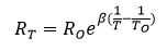
where RT=Resistance of thermistor at Temperature ‘T’
RO=Resistance of Thermistor at Temperature ‘TO’
T0=Reference Temperature to be set (generally 25°C)
β is a constant, its value is dependant on the characteristics of the material. The nominal value is taken as 3500.
BODY OF THE CONTENT:
- Software used :Simulink
My Doorbell Model:
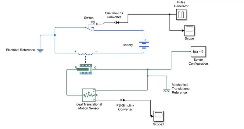
- At first, a pulse is fed to the switch of the Doorbell circuit with the following parameters:
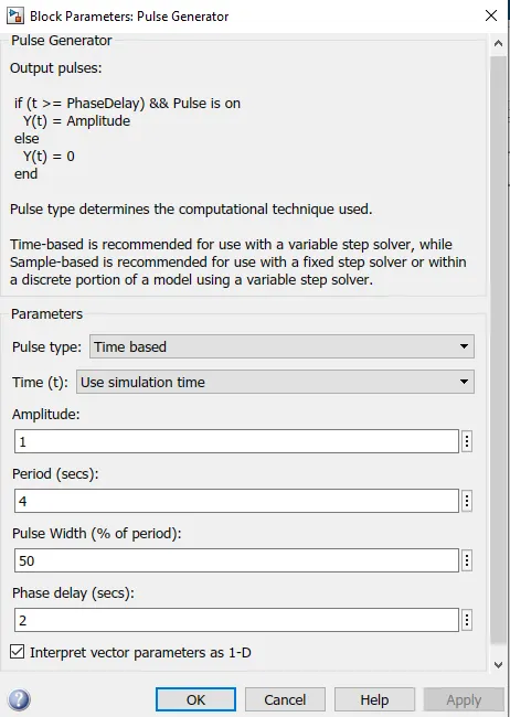
- The parameters have been based on the conditions as mentioned in the challenge question.
- After the switch gets on, current passes the circuit which comes from the battery and the after the electric current is fed to the solenoid, magnetic fields are induced in and around the solenoid.
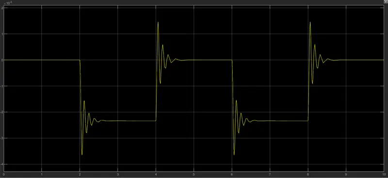
- Due to the sudden production of the magnetic field in the solenoid, the plunger which is attached to the spring in the same solenoid suddenly starts moving towards the left due to the magnetic force acting on the plunger and due to the movement of the plunger, the spring gets compressed. Since the process is very sudden, there is sudden unstable reciprocation of the of the plunger until over time it gets to a stable albeit compressed position as the magnetic force is still acting on the plunger.
- Again as the switch is turned off, the magnetic force is removed suddenly and the spring suddenly pushes back the plunger back to its normal position and in this process the spring suddenly expands. Since this process is very sudden, there is sudden unstable reciprocation of the plunger until over time it gets back to its stable original position.
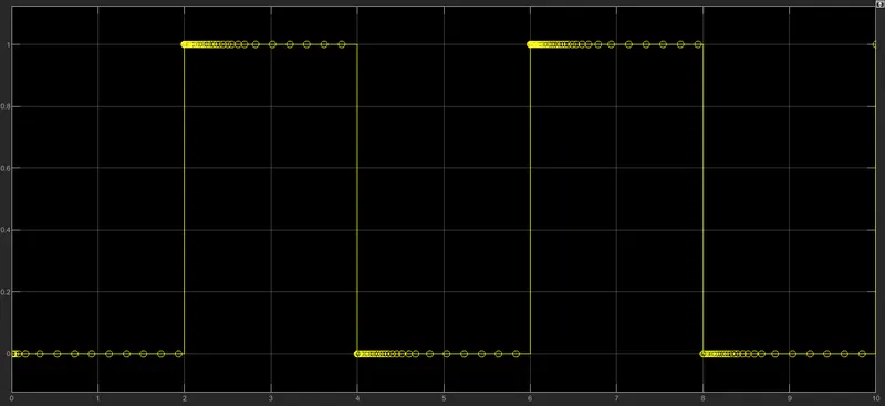
- This process keeps happening every 2 seconds due to the input parameters given to the pulse generator block and these pulses being given as input to the switch of the circuit.
- In the circuit, the plunger movement corresponds to the movement of the spring attached to it. A mechanical translational sensor attached to the solenoid is used to sense/detect the position of the spring/plunger w.r.t. to the pulses fed to the circuit over time.
- The variation in the movement of the spring/plunger w.r.t time can be seen via the scope block connected to the mechanical translational sensor.
Thermistor:
- Attached below is my thermistor model to be used as a temperature sensor and based on the output , a switch gets turned on/off based on a particular threshold value:
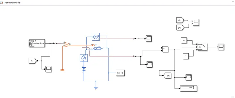
- For this project, the threshold temperature value for turning on a switch is 25°C.
- The Thermistor senses temperature being fed to it as an input and the resistance of the thermistor corresponds according to the temperature being sensed by the thermistor. The relation between the resistance and temperature in a NTC thermistor has already been discussed in the ‘GOVERNING EQUATIONS & RELEVANT THEORY SECTION’.
- On the basis of the temperature signal fed to the thermistor, the resistance values are being generated in the thermistor. Since in Simulink, there is no sensor block of measuring the resistance in a circuit, I have used the current sensor (ammeter) and the voltage sensor (voltmeter) to find out the resistance being generated in the thermistor.
- According to Ohm’s Law, V=IR where V-> Voltage drop across the resistor/thermistor, R-> Resistance in the thermistor and I-> Current flowing through the resistor. Using the Voltage drop across the thermistor being sensed by Voltage sensor and current flowing across the thermistor being sensed by the current sensor, the voltage values from the Voltage sensor are divided by the current values from the current sensor for the same time to get the resistance values at the thermistor.
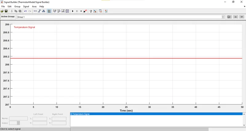
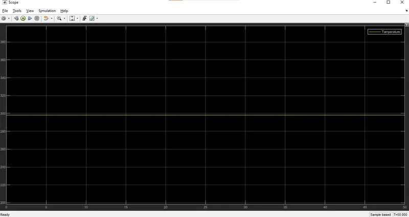
- Now in order to get the threshold value of resistance in thermistor corresponding to the temperature of 25°C being fed to the thermistor, a scope block has been attached to the division block (which divides Voltage by the Current from the circuit containing only the thermistor). In the signal generator block instead of feeding the signal as asked in the challenge question, a constant temperature signal of 25°C (298.15 K) is generated and fed to the thermistor and the resistance value corresponding to this temperature is seen in the scope block(A display block can also be used for this case)
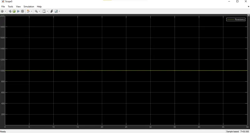
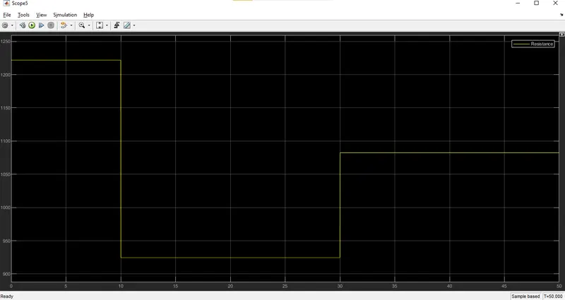
- As seen from the scope block/display block connected to the division block (calculating V/I) the threshold value for resistance has come out to be 1000 ohm.
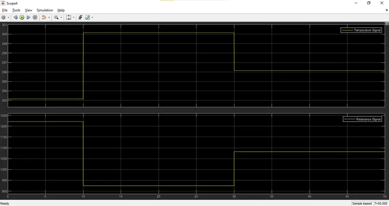
- It is to be noted that resistance varies inversely w.r.t. temperature (i.e. Resistance decreases as Temperature increases) as the thermistor is a NTC type. According to the challenge question the switch gets turned on if temperature goes ABOVE 25°C (298.15 K) otherwise it remains off. In terms of Resistance it corresponds to the fact that switch gets turned on if the resistance in the thermistor goes BELOW 1000 ohm otherwise it remains off.
- Now the signal waveform according to the one given in the challenge question is generated in the signal generator in the block and a switch block is connected to division block (calculating Resistance in thermistor w.r.t. Time).
- In the switch block, the parameters given are:
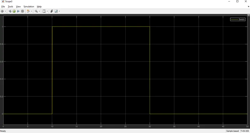
If the Resistance values goes below 1000 ohms then an output value of 1(corresponds to switch on) is generated otherwise an output value of 0(corresponds to switch off) is generated.
- The output signal from the switch block is connected to a scope block and the 2D plot generated in the block is observed.
RESULTS:
Doorbell:
- Input Pulse given to the switch:
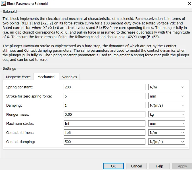
- Solenoid parameters:
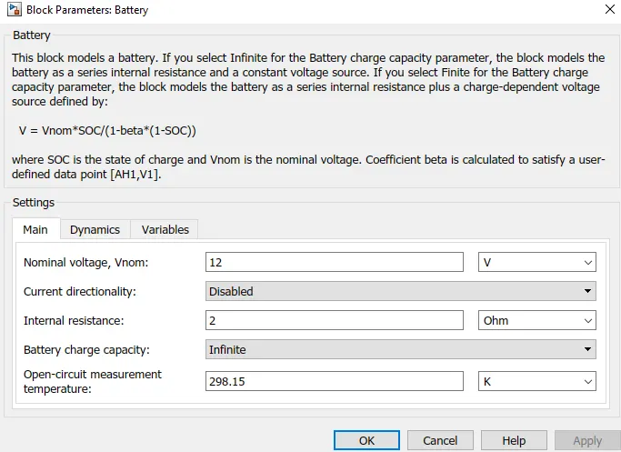
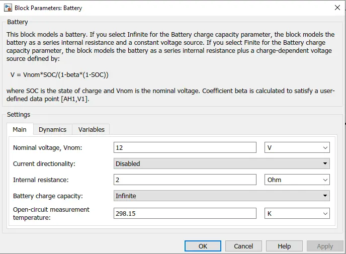
- Battery Parameters:
- Output position variation of the plunger/switch:
Thermistor:
Case 1: Finding the threshold Resistance for the given Threshold Temperature 25°C/298.15 K (based on which switch will be off/on):
- Temperature Signal built in the Signal builder:
- Input Temperature signal given to the Thermistor:
- Battery Parameters:
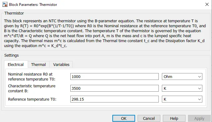
- Thermistor parameters:
- Resistance output signal obtained from the Scope block attached to the Division block:
Case 2: Applying the conditions of building the Temperature signal as mentioned in the question and observing the output:
- Temperature Signal built in the Signal builder:
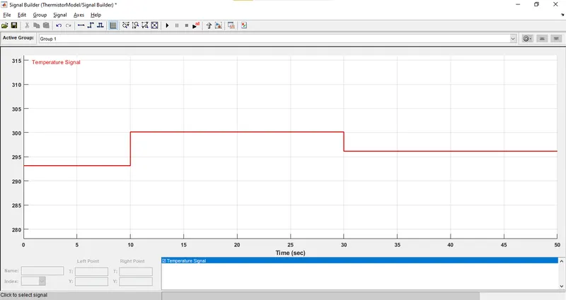
- Input Temperature signal given to the Thermistor:
- Battery Parameters:
- Thermistor parameters:
- Resistance output signal obtained from the Scope block attached to the Division block:
- Comparison of the Temperature and the corresponding the Resistance for the given time period of 50 seconds:
- Output from the switch Block based on the Threshold Resistance value:
CONCLUSION:
- Using Simulink, the simulation of the Doorbell circuit and the Thermistor circuit was done.
- The position of the plunger/spring in the solenoid was observed when the doorbell circuit was switched on and off.
- The Resistance and the state of the switch (which can be connected to another device like a fan) was studied when various Temperature values were being sensed by the Thermistor.
REFERENCES:
- https://byjus.com/physics/working-of-electric-bell/
- https://home.howstuffworks.com/home-improvement/repair/doorbell3.htm
- https://skill-lync.com/knowledgebase/thermistor-challenge
- My Doorbell Model:https://drive.google.com/file/d/1Mym4BsgXA2qMnege77NkSWiQv5URcGqR/view?usp=sharing
- My Thermistor Model:https://drive.google.com/file/d/1Y_4W1MAxl8gyUdS-UX0_FTsasJjbZtxG/view?usp=sharing