Week-6 Challenge: EV Drivetrain
Q1:-
Usually, in power electronics, there are 4 types of converter
- Rectifier (AC-DC converter)
Her input will be of ac either single phase or 3 phase and this will have transformer and output will have diode or diodes. This will be followed by a filter. The output will be pure DC.here component will be selected based upon the Rating of the system and its operating voltage.
this will be available in a controlled rectifier or uncontrolled rectifier.
Usually, this will be used in a board charger in BEV or an HEV.
- DC-DC Converter
Here both sides will be DC and it consists of sides DC and we can able to step up or step down both voltages and current. it has the following types
Buck converter:-input will have greater voltage while output will be having lesser voltage.
Boost converter:-input will have lesser voltage while output will be having greater voltage.
Buck-boost converter:-here output voltage may be greater or lesser compared to the input voltage.
here to switch some devices will be used such as MOSFET, IGBT and transistor and all.
Now to drive this switched driver will be used.
usually will be used in the Power distribution unit of EV
- DC-AC Converter (inverter)
here input will be of AC and output will be of DC.and depending upon the configuration, And its power rating its components will be decided.
It can be serrated into 2 groups
1. voltage service inverter
2. current source inverter
it also has a semiconductor switch like MOSFET, IGBT and all.
here it is done usually associated with an IC.
usually used for motor controller unit.
- AC-AC converter
Here instead of going both will be of AC, But some power modulation will happen within a circuit.
application;-Used in lamp control, motor speed control.
Q2:-now given parameters are
V-72V
current -400A
Ra-0.5 ohm
K phi =0.7
switching frequency 400 Hz
Tv=24.7+(0.0051) omega^2
now subsuting all of the value which we had above we will be getting
Vo=Vin*duty cycle
Vo=72*0.7
Vo=50.4V....................1
omega =`(Vo div K phi) - [(Ra div (K phi ^2)).T]`
and substituting value e are going to get
`omega=(50.4 div 0.7)-[(0.5 div 0.49)*T]`
`omega=72-1.020Tm`
if Tm=T
then
TV=24.7+0.051w*w
24.7+0.051w*w=70.5605-0.98w
`0.0051omega^2``0.0051omega^2+0.91omega-45.86`
now solving using Matlab,
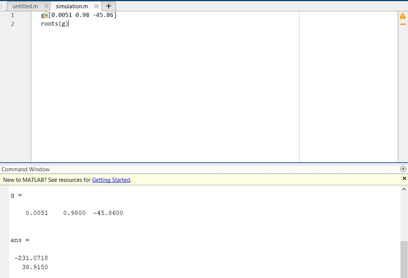
Fig 1:-output of the equation
since `omega=38.93`
so that output will become
Tv=25.47 Nm.
Q3:-model will be as shown below
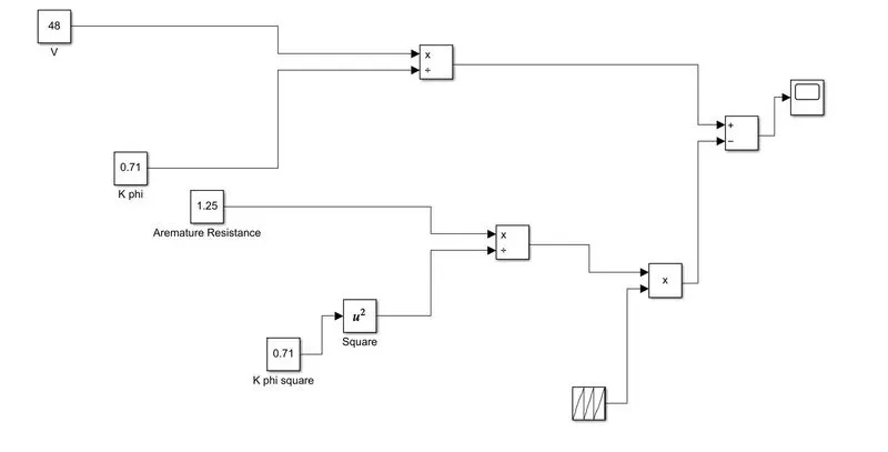
Fig 2:-Model for the scheme
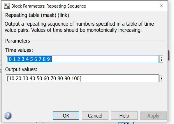
Fig 3:-Repeating sequences
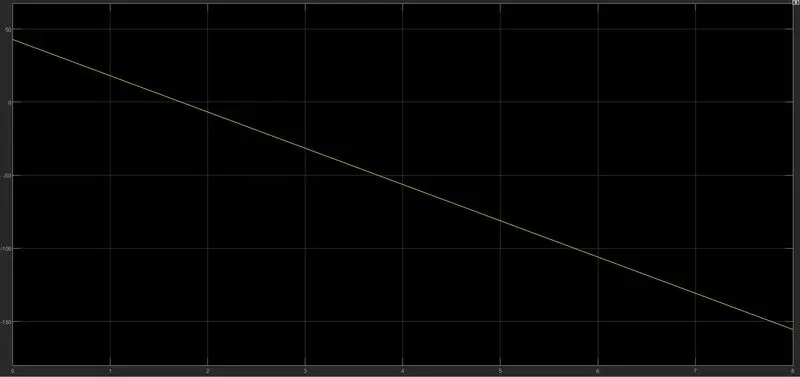
Fig 4-Output of the model.
here we selected the voltage will be of 48V and K pie has considered as 0.7 and we need to give torque so I had chosen preparing sequence.
the output will be given as linearly decreasing and it is from the basic equation.
Q4:-answer is a given perspective
|
Sl No |
Parameter |
Brushless inductor motor |
Induction motor |
|
1 |
Stator |
similar |
Similar |
|
2 |
Rotor |
Inverter control with digital control |
Inverter control |
|
3 |
Sensor |
Absolute position |
Speed sensor |
|
4 |
Heat generated |
More |
Less |
|
5 |
Power factor |
Unity |
0.85 |
|
6 |
Losses |
Lesser |
More |
|
7 |
High performance |
Desired |
Not Desired |
|
8 |
Commercial feasibility |
Costly |
Cheaper |
|
9 |
Control |
Not so difficult |
Difficult |
Result
- Different types of controllers were understood
- An equation is derived and the entire mechanism with respect to the duty cycle and voltage is known
- A graph is plotted for a given function and its observation was discussed
- according to the author perspective entire working of induction motor and brushless dc motor is known.