Week-6 Challenge: EV Drivetrain
1. Which types of power converter circuits are employed in an electric and hybrid electric vehicle?
Converter:
The converter is an electrical circuit that accepts a DC input and generates a DC output of a different voltage, usually achieved by high frequency switching action employing inductive and capacitive filter elements.
Power Converter:
A power converter is an electrical circuit that changes the electric energy from one form into the desired form optimized for the specific load. A converter may do one or more functions and give an output that differs from the input. It is used to,
- increase or decrease the magnitude of the input voltage
- invert polarity,
- produce several output voltages of either the same polarity with the input, different polarity, or mixed polarities such as in the computer power supply unit.
The DC-to-DC converters are used in a wide range of applications including computer power supplies, board-level power conversion and regulation, dc motor control circuits, and much more.
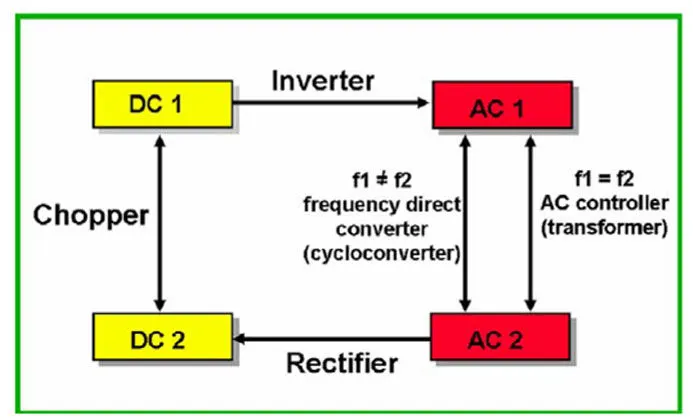
The converter acts as the link or the transforming stage between the power source and the power supply output. There are several kings of converters based on the source input voltage and the output voltage and these falls into four categories namely
- AC to DC converter known as the Rectifier,
- AC to AC cycloconverter or Frequency Changer,
- DC to DC voltage or Current Converter or Chopper and
- DC to AC converter known as the Inverter.
The converter uses non-linear components or passive elements such as the semiconductor switches, and linear reactive components or active elements such as the inductors, transformers, and capacitors for intermediate energy storage as well as current and voltage filtering.
The size, weight, and cost of the converter are largely determined by these components.
There are basically three converter circuits that are widely used in DC-to-DC converters. Those converter circuits are widely known as;
- Buck
- Boost, and
- Buck and Boost.
These configurations are the most used topologies due to their simplicity and use of fewer components. Each has its advantages and drawbacks which determines the suitability for any specific application.
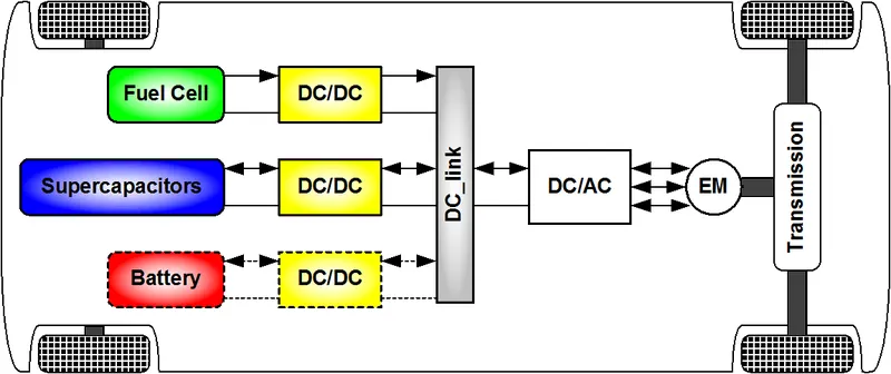
In electrical engineering, a DC-to-DC converter is a category of power converters, and it is an electric circuit that converts a source of direct current (DC) from one voltage level to another, by storing the input energy temporarily and then releasing that energy to the output at a different voltage. The storage may be in either magnetic field storage components (inductors, transformers) or electric field storage components (capacitors).
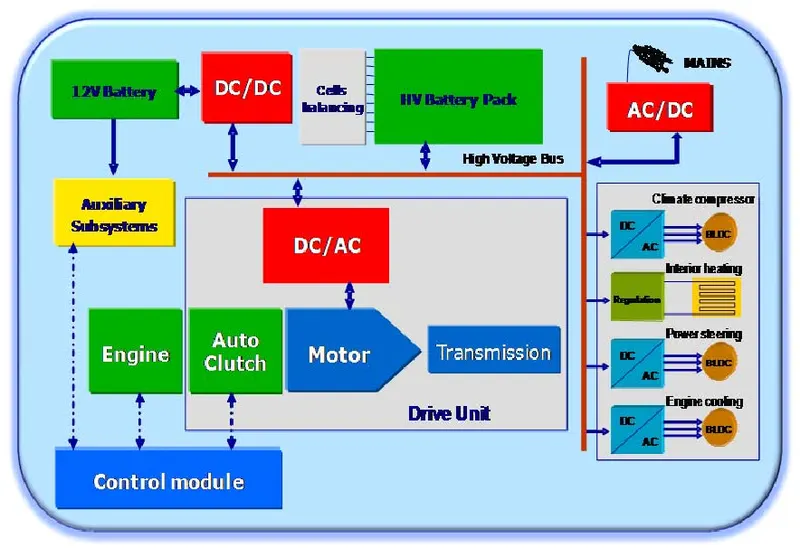
DC/DC converters can be designed to transfer power in only one direction, from the input to the output. However, almost all DC/DC converter topologies can be made bi-directional. A bi-directional converter can move power in either direction, which is useful in applications requiring regenerative braking.
The different types of power converter circuits that are employed in electric and hybrid electric vehicle are.
- AC to DC converter or Rectifier
- DC to AC converter or Inverter
- DC to DC converter or Chopper
- AC to DC converter or Rectifier:
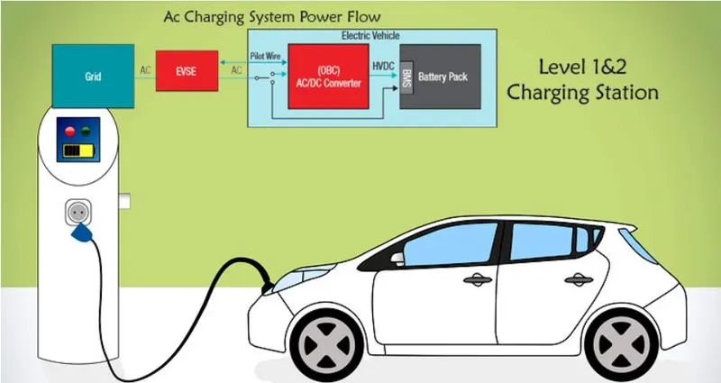
- Mainly used as an On-Board Charger
- On-board charging systems (OBCs) convert AC power from an external charging source into a DC voltage that is used to charge the battery pack in the vehicle.
- OBCs also perform other functions including charge rate monitoring and protection. Industry charging standards for OBC systems are shown in the table below.
- AC Level 2 OBCs and some Level 1 systems require isolation.
- With DC Fast Chargers, which plug directly into the quick charging connector, OBCs are bypassed
- DC to AC converter or Inverter:
- A power inverter, or inverter, is a power electronic device or circuitry that changes direct current (DC) to alternating current (AC). The resulting AC frequency obtained depends on the device employed. Inverters do the opposite of "converters" which were originally large electromechanical devices converting AC to DC.
- The input voltage, output voltage and frequency, and overall power handling depend on the design of the specific device or circuitry. The inverter does not produce any power; the power is provided by the DC source.
- A power inverter can be entirely electronic or maybe a combination of mechanical effects (such as a rotary apparatus) and electronic circuitry. Static inverters do not use moving parts in the conversion process.
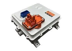
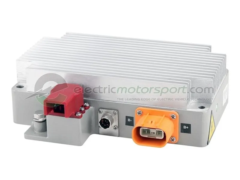
- DC to DC converter or Chopper:
- Mainly used as a Chopper either to Step Up or Step Down the DC voltage as per requirement.
- DC-DC converters can be used to interface the elements in the electric power train by boosting or chopping the voltage levels. Due to the automotive constraints, the power converter structure must be reliable, lightweight, small volume, with high efficiency, low electromagnetic interference, and low current/voltage ripple.
2. An Electric Vehicle's powertrain with 72V battery pack in shown in the diagram below. The duty ratio for acceleration operation is 'd1' and for the braking operation the duty ratio is 'd2'.
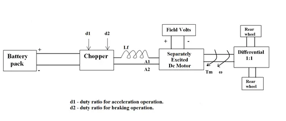
The other parameters of the electric vehicle is given below,
Motor and Controller Parameters:
- Rated Armature voltage= 72 V
- Rated armature current= 400 A
- Ra= 0.5Ω
- KΦ= 0.7 Volt second
- Chopper Switching frequency= 400 Hz
The vehicle speed-torque characteristics are given by the below equation

What is the EV steady-state speed if the duty cycle is 70%?
Given:
Rated Armature voltage, VA = 72 V
Rated armature current= 400 A
Ra= 0.5Ω
KΦ= 0.7 Volt second
Chopper Switching frequency= 400 Hz
For Duty Cycle, δ = 70%
Voltage = VA × δ
= 72 × 0.7
= 50.4 V
We know,
Torque, T = KΦ/RA*[ VA - KΦ*ω]
By Substituting the given values,
Torque, T = `(0.7/0.5) * (50.4 - 0.7w)`
= 1.4 × (50.4 – 0.7 ω)
= 70.56 – 0.98 ω
T = 70.56 – 0.98 ω and
Tv = 24.7 + 0.0051 ω2 (Given)
At T = TV ;
70.56 – 0.98 ω = 24.7 + 0.0051 ω2
Or, 0.0051 ω2 + 0.98 ω +24.7 -70.56 = 0
Or, 0.0051 ω2 + 0.98 ω – 45.86 = 0
i.e., ω = 38.915 or −231.072
Since Speed cannot be negative, we will consider that the EV steady-state speed, if the duty cycle is at 70%, is
ω = 38.915 rad. S-1 or 371 rpm
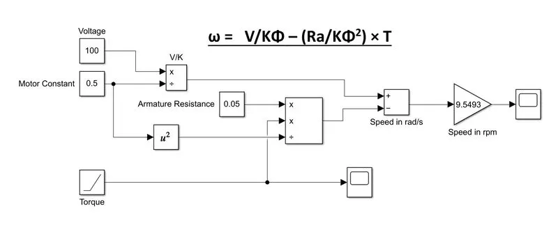
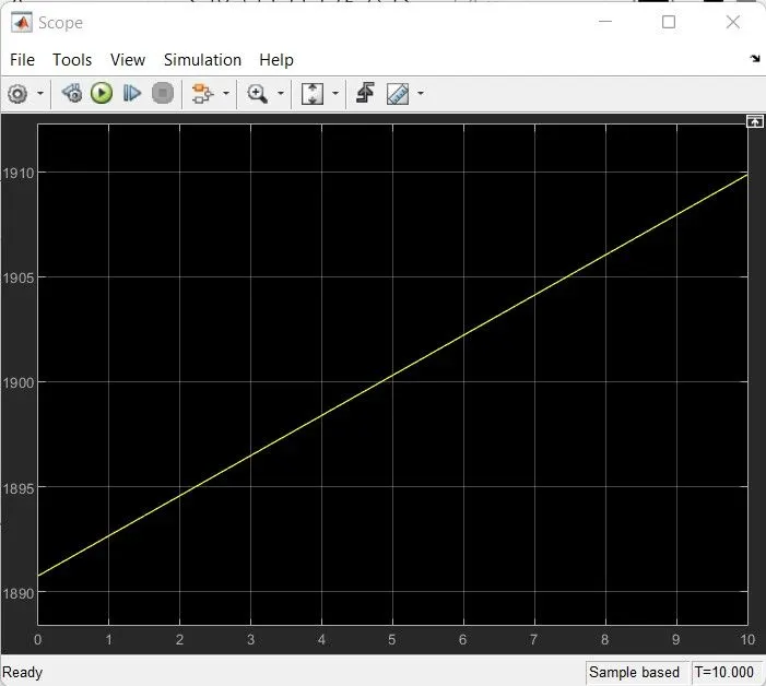
3. Develop a mathematical model of a DC Motor for the below equation using Simulink.
ω= V/KΦ – (Ra/KΦ2) × T
4. Refer to the blog on the below topic: Induction Versus DC brushless motors by Wally Rippel, Tesla
Explain in brief the author’s perspective.
The author’s perspective for the blog topic, Induction Versus DC brushless motors by Wally Rippel, Tesla is as follows,
- Wally Rippel believes that there is no one best engine type, but different types of engines to suit personal requirements based on price and performance and that is also the case with electric vehicle drives
- He points out the evolution of components in EV technology from Lead-acid batteries, DC brushed motors, and contactor controllers to Lithium-ion batteries, BLDC and Induction motors to even inverters.
- He strongly believes that both induction and BLDC motors will have tough competition in the coming years because each will have its loyal proponents and religious detractors.
- He compares the design of both BLDC and Induction and observes that its only differences are in Rotors
- He also adds the importance of an Inverter in variable speed application of Induction motor to operate flawlessly
- He even comments on the efficiency and performance characteristics of both BLDC and Induction motors
- He explains that BLDC generates much less Rotor copper loss and its ability to operate at unity power factor helping to achieve peak point efficiency whereas the best power factor available for Induction motor is around 85% making it a few percentages point lower efficient
- He also criticizes the drawback of BLDC motors which is the difficulty in lowering its magnetic field strength during low torque values to achieve the best efficiency because to minimize the magnetic field strength, it is also required to minimize the eddy and hysteresis loss.
- Furthermore, he compares the cost, performance, and reliability of both motors as Induction motor is Cheaper due to the absence of PM’s, Performance-oriented but requires complex algorithms for controlling and achieving stability is difficult causing increased development cost, Whereas BLDC is expensive but very easy to control, also very efficient and high stability.
- The author concludes that there isn’t any winner because he believes that BLDC continues to run the HEV and PHEV segments while Induction motors dominate high-performance EV segments. But, he anticipates that both Induction and BLDC motors live and work side by side during the coming golden era of hybrid and electric vehicles.