Week-6 Challenge: EV Drivetrain
AIM: To study the Electric Vehicle Drivetrain system as per the given conditions.
OBJECTIVE:
- List the type of power convertors used in electric and Plug-in hybrid electric vehicles.
- Calculate the Steady state speed of the EV when Duty cycle is 70%.
- Prepare a Simulink block set for Motor speed calculation.
- Study the given blog and explain in brief about authors perspective.
1. Which types of power converter circuits are employed in electric and hybrid electric vehicle?
A power converter is an electrical circuit that changes the electric energy from one form into the desired form optimized for the specific load. A converter may do one or more functions and give an output that differs from the input. It is used to increase or decrease the magnitude of the input voltage, invert polarity, or produce several output voltages of either the same polarity with the input, different polarity, or mixed polarities such as in the computer power supply unit.
The converter uses non-linear components such as the semiconductor switches, and linear reactive components such as the inductors, transformers and capacitors for intermediate energy storage as well as current and voltage filtering.
Types of Power converter circuits:
- Diode rectifier
- AC-DC converters (controlled rectifier)
- AC-AC converters (AC voltage controller)
- DC-DC converters (DC choppers)
- DC-AC converters (Inverters)
- Static switches
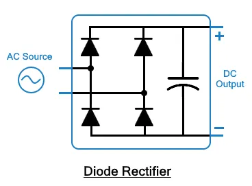
1. Diode Rectifier
This circuit (Diode rectifier) converters AC power into fixed DC power. The applied input voltage can be single-phase or three-phase. The input alternating voltage is converted into a steady & smoother DC output.
2. AC-DC Converters (Controlled Rectifier)
This type of converters converts the applied AC signal into DC signal using controlled switches (Thyristors). For this reason, the converter is also known as a controlled rectifier. Four natural commutated thyristors are used in this circuit instead of diodes.
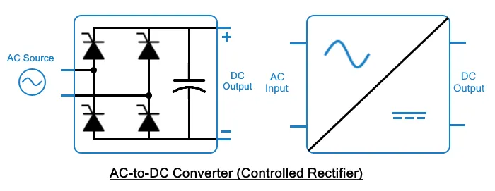
The average output voltage of the converter can be controlled by firing delay or by varying the conduction time. The applied input can be single-phase or three-phase.
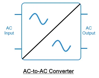
3. AC-AC Converters
These converters convert the fixed AC source into variable AC output voltage. A single-phase AC-AC converter is shown in the figure with a TRIAC. By varying the conduction time of TRIAC, the output voltage of converter can be controlled directly. AC-AC converters are also known as AC voltage controllers.
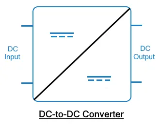
4. DC-DC Converters
DC-DC converters convert or change the voltage level of applied DC input into a DC output. These converters are also known as choppers, or a transistor chopper, or switching regulator.
The average output voltage of the converter circuit can be directly controlled by changing the conduction time of the controlled switch. The conduction time t of the switch is the product of the duty cycle and chopping period.
t = DT
Where D is the duty cycle of the chopper and T is the chopping period.
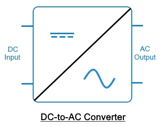
5. DC-AC Converter
DC-AC converters convert the input DC power into AC power. These converters are also known as inverters. There are a lot of different types of inverters; however, a typical Inverter uses four switches or thyristors. The output voltage of the circuit can be directly controlled by changing the conduction time of the switch using the switching circuit.
6. Static Switches
Static switches are a type of converter that connects the load with the source & also provides an abrupt switching between the sources. In UPS (Uninterruptible Power Supply), there are a various number of different conversion stages that cascaded for producing different output voltage levels.
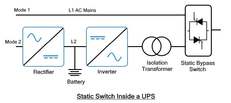
There are two source lines as shown in the figure, L1 and L2. L1 supplies the normal AC from the AC mains or AC outlets via the static switch while the rectifier charges the backup battery from the line L2. The emergency power to the load from the battery is inverted and then feed to the load via an isolation transformer. The supply to the switches can be AC or DC. These switches are known as static switches or DC switches.
Electric Vehicle
Hybrid Electric Vehicle
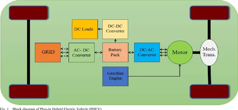
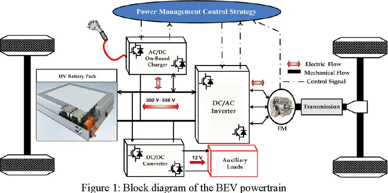
For Electric Vehicle and Hybrid Electric Vehicle same type of power converters are used
- In the On-board charger AC-DC converter is used to charge the battery from the external AC source.
- DC from the battery is Converted to AC to run the Motor with the help of DC-AC Inverter.
- To run the Auxiliary loads DC-DC Convertor is used.
2. An Electric Vehicle's powertrain with 72V battery pack in shown in the diagram below. The duty ratio for acceleration operation is 'd1' and for the braking operation the duty ratio is 'd2'.
The other parameters of the electric vehicle is given below,
Motor and Controller Parameters:
Rated Armature voltage= 72 V
Rated armature current= 400 A
Ra= 0.5Ω, KΦ= 0.7 Volt second
Chopper Switching frequency= 400 Hz
What is EV steady state speed if duty cycle is 70%?
Modes of operation
- Steady State
- Acceleration including starting
- Deceleration including Stopping (braking)
Steady state operation takes place when motor torque equals the load torque. The steady state operation for a given speed is realized by adjusting of steady state motor speed-torque curve such that the motor and load torque are equal at this speed.
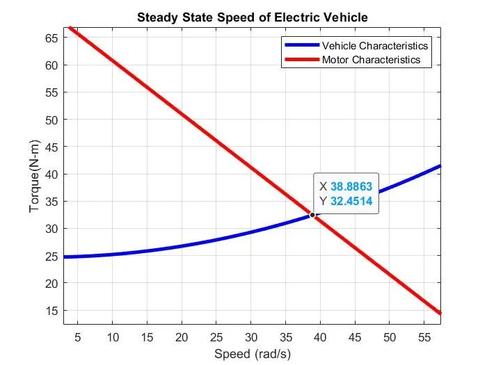
I have Calculated the Steady state speed of Electric Vehicle in two methods
- Hand Calculations
- MATLAB program
Hand Calculations
Given data
Rated Armature voltage (Va) = 72 V
Rated armature current (Aa) = 400 A
Ra = 0.5Ω
KΦ = 0.7 Volt second
Chopper Switching frequency (F) = 400 Hz
Duty cycle (D) = 70% = 0.7
Voltage supply (V) when duty cycle is 70 %
V = Va * D
V = 72 * 0.7
V = 50.4 v
Wkt
Time = 1 / F = 1 / 400
Time (t) = 0.0025
Wkt
D = Pw / t
Pw = D * t = 0.7 * 0.0025
Pulse width (Pw) = 0.00175
Motor Torque (Tm)
Tm = (KΦ* V – KΦ2 * ω) / R
Tm = KΦ (V – KΦ * ω) / R N-m ………….1
Were
T = Motor Torque (N-m)
V = Voltage supply
ω= Rotational Speed (rad/s)
KΦ = Motor/Torque Constant
R = Resistance
Vehicle Torque (Tv)
Tv = 24.7 + (0.0051) ω2 ……………...2
Wkt
Steady state of Electric vehicle occurs when the Motor and Vehicle (load) torque are equal
therefore
Tm = Tv
KΦ (V – KΦ * ω) / R = 24.7 + (0.0051) ω2
0.7 (50.4 – 0.7* ω) / 0.5 = 24.7 + (0.0051) ω2
35.28 - 0.49 ω / 0.5 = 24.7 + (0.0051) ω2
35.28 - 0.49 ω = 12.35 + 0.00255 ω2
0.00255 ω2 + 0.49 ω – 22.93 = 0
ω = 38.9149 rad/s
therefore
Tv = 24.7 + (0.0051) * (38.914)2
Tv = Tm = 32.424 N-m
MATLAB Program:
clear all
close all
clc

% inputs
% Rated Armature Voltage-V
Va = 72;

% Rated Armature Current-A
Aa = 400;

% Armature Resistance
Ra = 0.5;

% Motor Constant
K = 0.7;

% Duty cycle 70%
D = 0.7;

% Armature voltage at 70% duty cycle
Vo = Va * D;

% Motor angular speed (W)
W = linspace(1,60,300);

% Vehicle Torque equation
Tv = 24.7 + ((0.0051).*W.^2);

% Motor Torque equation
Tm = (((K*Vo)-(K^2.*W))/Ra);

% Plotting Tv-W and Tw-W

plot(W,Tv,'linewidth',3,'color','b')
hold on
plot(W,Tm,'linewidth',3,'color','r')
xlabel('Speed (rad/s)');
ylabel('Torque(N-m)');
title('Steady State Speed of Electric Vehicle');
grid on
legend ('Vehicle Characteristics','Motor Characteristics');Results:
3. Develop a mathematical model of a DC Motor for the below equation using Simulink.
ω= V/Kϕ - Ra / Kϕ^2. T
Simulink model for DC Motor, Speed (W) formula in rad/s
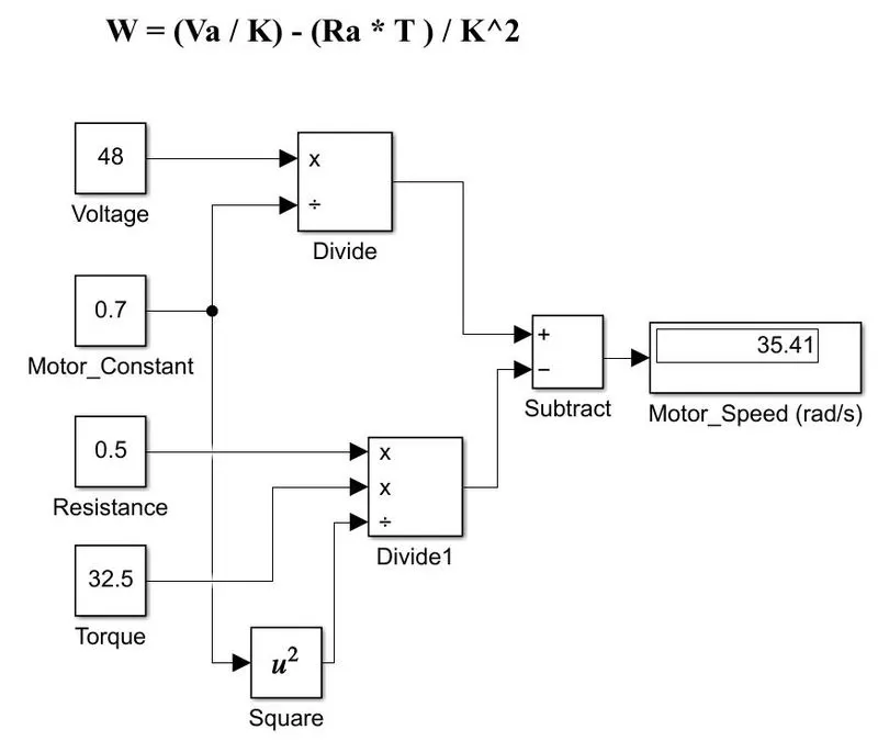
We can observe that as the voltage increases the Motor speed also increases by keeping all the other parameters constant.
Here I have defined the parameter values in ‘constant block’ only,
We can also define the values by taking ‘gain block’, first we have to define in the MATLAB command window which will store these values in Workspace. Finally, we can give the name of the parameter in the gain block.
4. Refer to the blog on below topic:
Induction Versus DC brushless motors by Wally Rippel, Tesla
Explain in brief about author’s perspective.
Authors main intension is to explain and Compare the DC Brushless Motor and Induction Motor in the field of Hybrid electric and Electric Vehicles domain.
|
Brushless DC Motor |
Induction Motor |
|
It can not start under load (Not self-starting) |
It can start under load (self-starting) |
|
These motors cannot directly compatible with conventional utility power |
These motors can directly compatible with conventional utility power |
|
Separate DC source is required for rotor excitation |
Here rotor gets excited by the induces e.m.f, no separate source is required. |
|
Speed control is not possible |
Speed control is possible |
|
Torque performance is high |
Torque performance is low |
|
It requires Absolute position sensor |
It requires only speed sensor |
|
Rotor generated less heat |
Rotor generated more heat |
|
Cooling is easier and Peak Point efficiency is high |
Cooling is easier and Peak Point efficiency is slightly lower than Brushless DC Motor |
|
It can operate at Utility power factor of 85% |
It can operate at Utility power factor of 80% |
|
Used when low and medium performance is required |
Used when high performance is required |
|
Average efficiency will be less |
Average efficiency will be better |
|
Motor is costly and requires frequent maintenance |
Cost of the motor is less |
|
By keeping speed constant if load increases, load angle also increases |
As load increases, speed keeps on decreasing |
|
Controlling the motor is easy |
It is difficult to control the motor |
We can conclude that, there is equal development and demand for these Brushless DC and Induction Motors. BLDC Motor can be dominated in the field of Hybrid and Plug-in Hybrid electric vehicles where as Induction Motors are used where high performance is required, they are used in Electric vehicle domain. The hardware is common for both the drives so, in the future we can see both the drives will run side by side in the field of Hybrid and Electric Vehicles.
CONCLUSION:
Hence, we have studied the EV Powertrain system, Explained and Solved the given conditions.
- Explained the different types of power convertors used in electric and Plug-in hybrid electric vehicles.
- Calculated the Steady state speed of the EV when Duty cycle is 70%
Steady state speed of the EV is 38.91498 rad/s , Torque of the motor and vehicle is 32.424 N-m
- Prepared a Simulink block set for Motor speed calculation.
- Studied the given blog and explained in brief about authors perspective.
In which the author compared Induction motor and Brushless DC motor with the application in Plug-in Hybrid and Electric Vehicles.
REFERENCE:
https://allabouteng.com/types-of-power-electronics-circuits-converters/