Week-6 Challenge: EV Drivetrain
1. Which types of power converter circuits are employed in electric and hybrid electric vehicle?
Types of Power Electronic converters
- AC to AC converter (Cyclo-Converter)
- DC to DC converter(Chopper)
- AC to DC converter(Rectifiers)
- DC to AC converters(Inverters)
From the above stated converters the possibility of being used by EV and HEV are Choppers, inverter and rectifier converters.
The rectifier can be used in the charging station which have AC as input and need DC output to charge the battery.
- Chopper
Choppers is nothing but DC to DC converter. It takes fixed DC voltage and provide variable DC output voltage.
There are various types of chopper available which can be used according application and the level of output voltage.
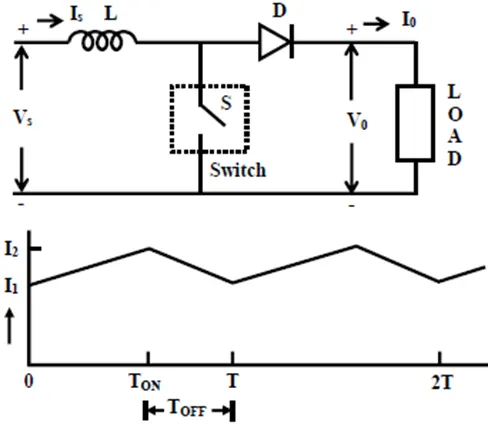
Fig: Step up chopper
The above figure is step up chopper which step up the given DC voltage.
- Rectifier
Rectifier is a converter which convert AC input to the DC output.
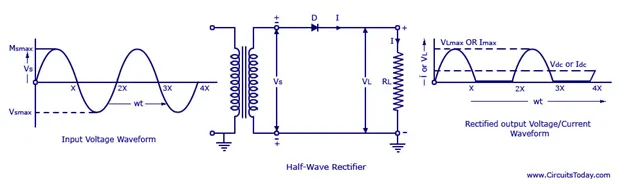
Fig: Half wave Rectifier
Above figure represent the half wave rectifier which is only capable of providing the outpit during positive halff cycle and hence the less average output voltage
- Inverter
Inverter Takes DC as input and provided AC voltage in the output.
Inverters can be used in the case of the BLDC motor, where for the operating and control the inverter is necessary.
Inverters are also useful where the battery is input source only and the motor is AC.
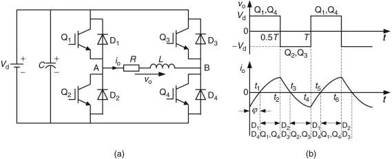
Fig: Full bridge inverter
The above figure is the full bridge inverter which provides square wave output from the DC input given. There many inverters available such as 120 and 180-degree conduction inverters, PWM inverters (single phase and three phase)
- Cyclo Converters
Again, Cyclo Converters are not employed in EV or HEV application.
Cyclo converters provide variable frequency from fixed frequency of given AC input. 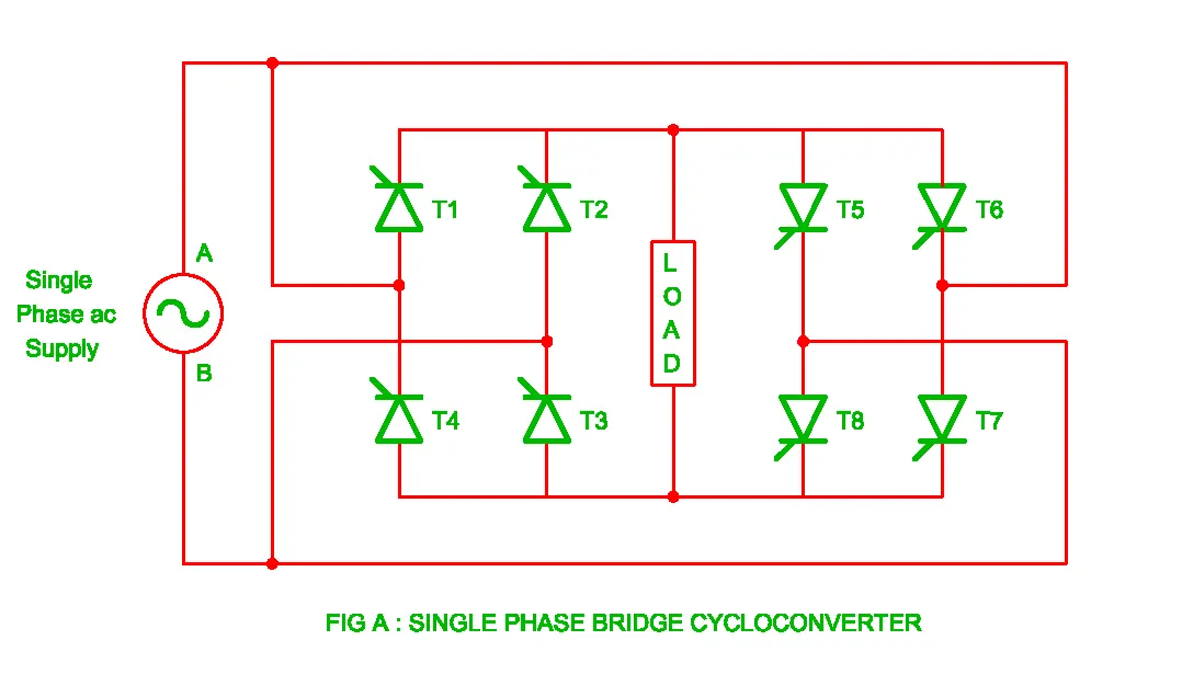
The given figure is single phase bridge cycloconverter which can be used for changing the frequency of the single phase AC input voltage.
2. An Electric Vehicle's powertrain with 72V battery pack in shown in the diagram below. The duty ratio for acceleration operation is 'd1' and for the braking operation the duty ratio is 'd2'.
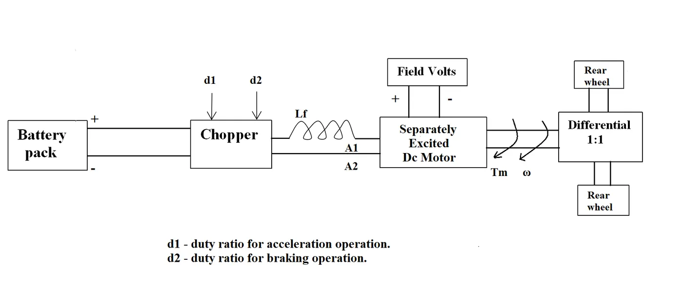
The other parameters of the electric vehicle is given below,
Motor and Controller Parameters:
Rated Armature voltage= 72 V
Rated armature current= 400 A
Ra= 0.5Ω, KΦ= 0.7 Volt second
Chopper Switching frequency= 400 Hz
The vehicle speed-torque characteristics are given by the below equation
 ___________________[1]
What is EV steady state speed if duty cycle is 70%?
Duty ratio =70%
lets consider a step down chopper
hence the output voltage `V_o = D V_s`
`therefore V_t= 0.7X 72=50.4 V`
we know the equation of speed of the DC motor
`omega = (V/(Kphi))-(R_a/(Kphi)^2)T`
making torque subject
`V- omega K phi = R_a /(Kphi)T`
`T= (V(Kphi)-omega(Kphi)^2)/R_a`______________________[2]
Comparing Bothe equation of Torque
Consider `Kphi=K_e`
`VK_e-omegaK_e^2=24.7R_a+0.0051R_aomega^2`
`omega^2 0.005 R_a + omega K_e^2 +24.7 R_a -V_t K_e =0`
Putting all the values and rearranging
`[2.55X10^-3]omega^2 +0.49 omega -22.93=0`
seems like it is quadratic equation
D=`b^2-4ac`
`=0.49^2 -4[2.55X10^-3(-22.93)]`
=0.473
`sqrtD=sqrt0.473 =0.688`
`omega =(-b+-sqrtD)/(2a)`
putting the values
`omega_1,omega_2=38.9 (rad)/sec,-230.98 (rad)/sec`
assuming that the motor rotates in clockwise or positive direction
hence the speed in steady state is
`omega=38.9 (rad)/sec`
Q_3:
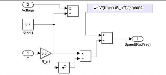
3. Develop a mathematical model of a DC Motor for the below equation using Simulink.
`ω = V/(K ϕ) -R_a/(K ϕ ^2) .T`
For implementing the above equation, the variables are given are Torque and The applied voltage to the motor. The slider gain and knob is used to vary tye variables.
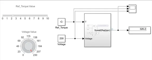
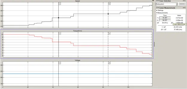
As seen from the graph the speed is increases with decreasing in the referece torque. An also the speed will decrease as the voltage decreases. The above graph and results ensure the equation of the dc machine is implemeted sucessfully.
Q_4:
Authors Perspective:
-The author describes the different aspects of the induction and the brushless DC motor for different application. Both the motor has its own advantages and the disadvantages.
-The choice between these motor varies according to the application and the requirement. Author describes that from the old time there are many change happened in the technology i.e, in batteries, motors. He describes that the battel between the both motor can continue for the years.
-In the closer look section author describes the working of the BLDC and induction motor.
-The BLDC motor is useless motor without the inverter arrangement. And also it has high cost due to use of Magnet (50$ per kg) and inverter arrangement.
- The induction machine can be connected to directly with utility grid. While BLDC needs inverter arrangement which again increases the effective cost.
- The construction is same for the stator for both induction and BLCD motor. The difference is in the rotor construction. The BLDC has permanent magnet in the rotor while the Induction motor has copper bars inserted in the rotor with shorted their ends.
- The induction motor has less torque performance as compared to BLDC motor. Induction motor has limited starting torque as compared to BLDC motor. Also the control of IM is difficult and to get the stability over the speed torque range is difficult.
Conclusion:
The author concludes that the BLDC will dominate in the hybrid EV and IM will dominate in the Pure EV. Both have advantages and disadvantages, hence the selection of both motor can be varying according to cost, level of control and other condition. Although the BLDC motor has high cost but it is worth to get the good level control compared to IM. There may be also possibility that the both the motor can work side by side in the upcoming golden era of HEV and EV.