Week-6 Challenge: EV Drivetrain
Objective:
1. Which types of power converter circuits are employed in electric and hybrid electric vehicles?
2. An Electric Vehicle's powertrain with a 72V battery pack in shown in the diagram below. The duty ratio for acceleration operation is 'd1' and for the braking operation the duty ratio is 'd2'.
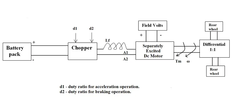
The other parameters of the electric vehicle are given below:
Motor and Controller Parameters:
Rated Armature voltage= 72 V
Rated armature current= 400 A
Ra= 0.5Ω, KΦ= 0.7 Volt second
Chopper Switching frequency= 400 Hz
The vehicle speed-torque characteristics are given by the below equation:

What is EV steady-state speed if the duty cycle is 70%?
3. Develop a mathematical model of a DC Motor for the below equation using Simulink.
ω">ω= V/Kϕ">ϕ -Ra/Kϕ">ϕ^2 .T
4. Refer to the blog on the below topic:
Induction Versus DC brushless motors by Wally Rippel, Tesla
Explain in brief about the author’s perspective.
Solution of Objective-1:
Electric vehicles are structured using different types of energy storage systems connected with various types of power electronic converters. Generally, energy storage systems are charged by taking current and voltage from the grid or charging stations through AC-DC converters. Afterwards, energy storage systems deliver the required energy to the motor to accelerate the vehicle. However, the power delivered by ESSs has unstable characteristics and considerable voltage drops. Thus, DC-DC converters play a key role in converting the unregulated power flow to a regulated one. The main purpose of using a controller in EV converters is to obtain steady-state and dynamic characteristics with short settling time, faster response and a few steady-state errors.
The complete classification of power electronics converter in EV and HEV are given below. The configuration of converters in EVs can be categorized into two groups: Isolated and Non-Isolated. The isolated DC-DC converters are suitable in EVs with low- and medium-power purposes, while the non-isolated converter is appropriate for EVs under medium- and high-power operation.
A. Non-Isolated Converter
Non-isolated bidirectional DC-DC converters include conventional DC-DC converters and interleaved DC-DC converters. Among them, conventional DC-DC converters are commonly employed due to their low cost, simple topology and easy control technique. The interleaved DC-DC converters have become popular due to their improved performance and efficiency.
- Cuk
The Cuk converter (CC) in EVs provides flexibility to regulate the output to be lower or higher in comparison to the input voltage. The CC features a lower output ripple and improved efficiency since it shares a single magnetic core. Besides, the CC has uniformity of the current at both the input and output terminal as well as continuous power transfer through the capacitor, leading to lower EMI radiation in the switches. Additionally, the CC implements an L-C filter which can regulate the peak-to-peak ripple current of the inductor more efficiently than a DC-DC bust-boost converter. However, the CC suffers from some losses due to high current stress on the switch and the largest number of reactive components.
- Switched-Capacitor Bidirectional Converter
The switched-capacitor bidirectional converter (SCBC) in EVs utilizes synchronous rectification to execute the turn-on and turn-off operations. The SCBC does not require extra components and has improved power conversion efficiency through the proper utilization of power switches. However, the SCBC has low voltage stress, a wide-reaching voltage gain and needs a smaller number of components. Besides, the SCBC suffers from a high ripple current and cannot offer high efficiency under widespread input to output voltages.
- Coupled Inductor Bidirectional Converter
A couple inductor bidirectional converter (CIBC) in EV’s provides high efficiency due to its high voltage gain stress. Besides, the CIBC has secondary leakage inductance which results in low reverse recovery of the output diode. Due to the usage of the heavy inductor in a power boost converter, a CIBC is much preferred as compared with multiple discrete inductors as it provides less iron loss and low inductor current ripples. Furthermore, the CIBC offers others benefits including voltage transformation, changing the impedance of a circuit and galvanic isolation. However, one of the limitations of couple inductor technology is the introduction of leakage inductance, causing resonance and voltage spikes.
- Quasi-Z-Source Bidirectional converter
Quasi-Z-Source Bidirectional converter (QZBC) is employed in EV’s due to its advantageous features, including simple topology, common ground and wide-ranging voltage gain. Generally, a conventional two-level QZBC is designed for EV operation. Besides, this converter offers low voltage stress with reasonable static and dynamic performance. However, it has the drawbacks of discontinuous input current and capacitance of high voltage stress.
- Multi-Device Interleaved Bidirectional Converter
The multi-device interleaved bidirectional converter (MDIBC) has become increasingly popular in EVs because of its advantageous features, including size, cost-effectiveness, high efficiency and lower ripples. The MDIBC in EVs maintains a constant magnitude in obtaining input current and the voltage ripples without an increase in the number of components like an inductor, capacitor and filter circuits. The reliability of the MDIBC is increased as compared with other conventional converters due to several factors, such as common heat sink, control scheme and mutual sharing of common DC link capacitor at the output, thus reducing shortcoming in terms of electrical faults and breakdowns. Furthermore, the overall efficiency, as well as effectiveness, are enhanced due to the utilization of regenerative braking power. In addition, the MDIBC is the preferred choice for high-power utilization in terms of interconnecting an HV battery to a DC link to the inverter. Nonetheless, the converter suffers from stability and sensitivity issues due to the transient state of the load current profile. Besides, the operation of the MDIBC is quite tricky to analyze under steady-state and transient conditions. Besides, components like a capacitor filter, heat sink and high-power inductor add extra weight to the converter.
B. Isolated Converter
The isolated bidirectional converter is designed using three primary phases, including DC/AC/AC. A high-frequency transformer (HFT) is utilized to lift the input voltage at higher values through the utilization of the intermediate AC stage. The HFT is responsible for providing galvanic isolation, leading to high voltage gain. The various isolated converters for EV applications are presented in the following sections.
- Push-Pull Converter
The DC-DC push-pull converter (PPC) topology in EV operation is based on the transformer action which transforms the power from one side of the circuit to the other side, i.e., primary to secondary. The PPC has various advantages, such as simplicity and higher efficiency due to lower peak current, resulting in lower conduction losses. Nonetheless, the PPC suffers from smaller filters as compared to other DC-DC converters. In addition, precautions are necessary while a switching operation is carried out since switches at the same time might potentially damage the converter due to the formation of a low impedance path and very high current.
- Flyback Converter
The flyback converter (FC) is an isolated DC-DC converter that originates from the buck-boost converter consisting of an inductor split into the form of a transformer. The energy is stored in the DC-DC FC during the ON state while energy is transferred in the OFF state. The FC is primarily applied in low-power applications due to its cost-effectiveness, multiple isolated outputs, high output voltages and electrical isolation characteristics. In addition, the FC eliminates inductive filters, thus saving cost and in turn providing filtered output. Furthermore, due to the elimination of freewheeling diodes, the FC can be utilized in applications with high load voltages compared with forward converters. However, the FC possesses several disadvantages, such as high ripple current, high input capacitance and high losses.
- Resonant Converter
A DC-DC resonant converter (RC) for EV powertrain applications consists of a combination of inductors and capacitors which is known as the resonant tank. The resonant tank is utilized in tuning to resonance at a given frequency. The RC comprises four switches, four diodes and two resonant frequency components, Lr and Cr. The magnetization inductance is used as the resonant element to execute the operation of the converter. Furthermore, the control in the RC under a no-load condition is resolved through the elimination of the magnetization current. The DC-DC RC for vehicular applications exhibits high efficiency and low switching loss. In addition, other benefits, such as zero circulating current and zero voltage switching operation, provide better operation and efficiency for the battery charging profile. Nonetheless, the RC has some limitations, such as heat problems due to magnetizing currents and the complex design of the transformer.
- Zero-Voltage Switching Converter
The zero-voltage switching converter (ZVSC) exhibits lossless switching, cold starting and contains less circuitry in comparison with other conventional converters for EV applications. The ZVSC is appropriate for the EV drivetrain due to its components’ reduced size, easy control technique and significant power density. Furthermore, the ZVSC can work without additional circuitry for soft switching and provide technical benefits, including friendly control methodology and higher efficiency. Besides, the ZVSC needs less control and accessory power in comparison to the full-bridge component. Nevertheless, the ZVSC experiences voltage stress across the switches in high-power applications. Furthermore, a large capacitor is required to limit ripples at the converter output. Due to the absence of a fault tolerance mechanism, the converter is not appropriate for operation above 10 kW. Multi-Port Isolated Converter The multi-port isolated converter (MPIC) integrates the multiple input sources to extract the benefit of an individual source. The power recovered in the MPIC during the process of regenerative braking can be utilized to feed the power back to the input source, thus improving the efficiency as well as the functionality of the converter. Nonetheless, the MPIC has some shortcomings. Due to an increase in the number of switches, synchronization becomes difficult. Furthermore, the weight of the converter also increases due to the presence of a bulky transformer.
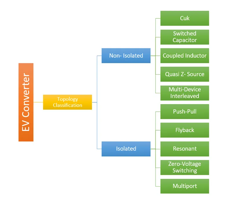
Fig.1: The comprehensive classification of EV converters
Solution of Objective-2:
As per given parameters of the electric vehicle
Rated Armature voltage= 72 V
Rated armature current= 400 A
Ra= 0.5Ω
KΦ= 0.7 Volt second
Chopper Switching frequency= 400 Hz
Duty cycle= 70%= 0.7
Voltage= Rated Armature voltage * Duty cycle
= 72 * 0.7 = 50.4 volt
As we know Torque- Speed characterstics of DC motor is `Tm= frac{V*Kphi){Ra}- frac{omega*Kphi^2){Ra}`
So, Tm= (50.4*0.7)/0.5 - (w*0.7^2) /0.5
Tm=70.56 - 0.98*w .........eqn-1
Given that , Tv= 24.7 + 0.0051*w^2 .......eqn2
Compare eqn-1 and eqn-2,
Tm=Tv
70.56 - 0.98*w = 24.7 + 0.0051*w^2
0.0051w^2 + 0.98w - 45.86 = 0 .......eqn3 (This is a quadratic equation)
Formula to find the roots of quadratic equation is,
`x=-b+-frac{sqrt(b^2-4ac)}{2a}`
Therefore, `w=-0.98+-frac{sqrt(0.98^2-4 ast (0.0051) ast (45.86))}{2 ast 0.0051}`
we get, w= 38.9150 and w= -231.071
So, Steady state speed of EV will be 38.9150 rad/sec.
Solution of Objective-3:
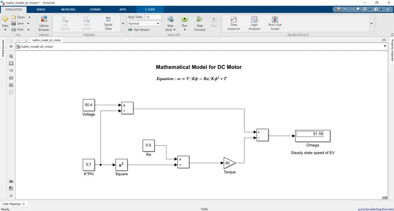
For, V= 50.4 volt
KΦ= 0.7 Volt- second
Ra= 0.5Ω
T= 40
Angular Speed(w)= 31.18 rad/sec
Solution of Objective-4:
Author’s viewpoint is that we have different configurations, types of vehicle and engine, but we cannot say that which is the best one. Not only conventional vehicles and cars are best as per their price and performance but also, applies to electric vehicles. Nowadays, lead-acid batteries were replaced by lithium-ion batteries, DC brush motors were replaced by DC brushless and induction motors, contractor controllers were swapped by modulating inverters. It might be possible that these elements can obsolete or it would become stable in forthcoming years, but we cannot predict the future.
DC brushless motors are ineffective without an “inverter” because without an inverter it cannot provides current control. In induction motors, currents are produced within the rotor which is approximately equivalent to the voltage that results in the speed difference. Induction motors do not require any ‘inverter” otherwise Tesla’s invention would have been useless. Induction motors are directly well-suited with utility power, and it is the main reason for their success. In short, a DC brushless motor produces no starting torque when directly connected to fixed frequency utility power. They really need the aid of an inverter whose “phase” is maintained in step with the angular position of the rotor. 3-Phase induction motors are very effective as per their applications, but they have some limitations such as:
- Inductions motors can operate only on AC, not on DC.
- Its shaft speed is equal to line frequency so that when it is used with conventional utility power, speed becomes constant.
- When operated from utility power, they have limited starting torque and somewhat limited running peak torque capabilities, when compared to DC type machines.
- Adding an inverter (without any feedback control) makes it possible to power an induction machine from a battery or other DC source; variable speed also becomes possible simply by adjusting the inverter frequency. Still, torque performance is low compared with DC machines.
- Adding some feedback loops in such a way that the inverter produces the exact frequency according to the motor’s requirement and the induction motor is now capable of competing with DC brushless motor for vehicle applications.
Around the 1990s, DC brushless drives were used in almost all-electric vehicles but today it is being used in hybrid electric vehicles. Both DC brushless and induction drives use motors having similar stators and 3-phase modulating inverters. The only difference is the rotors and the inverter controls. And with digital controllers, the only control differences are with control code. DC brushless drives require an absolute position sensor, while induction drives require only a speed sensor; these differences are relatively small.
One of the main differences is that the heat generation factor is low in DC brushless drives, so rotor cooling and peak point efficiency are high. It can also operate at a unity power factor, whereas an induction drive has a power factor of about 85% which means that the peak point energy efficiency for a DC brushless drive will be slightly higher than an induction drive. The strength of the magnetic field of permanent magnets is adjustable for an ideal brushless drive. At low speed, the vehicle needs high torque, in such case magnetic field strength (B) should be high so that inverter and motor currents can be maintained at their lowest possible values. This reduces the I2R losses and increases efficiency. At high speed, when torque requirement is low, the magnetic field (B) should be low so that eddy and hysteresis losses due to the magnetic field can also be reduced. In the ideal case, the magnetic field should be adjusted so that sum of eddy, hysteresis and I2 losses remain low but it is not possible. Induction drives have no magnets and B fields are adjustable which means that at lower loads the inverter can reduce voltage such that magnetic losses can be reduced, and efficiency can be increased. Thus, the induction drives when operated with a smart inverter has an advantage over DC brushless drives.
Another advantage of induction drive is that that as motor size increases, the magnetic loss does not increase but in DC drives when motor increases the magnetic loss increase and efficiency decrease. Thus, choosing induction drives will be the better option where high-performance is required. It might be possible that peak efficiency will be lower than DC brushless but average efficiency will be better. The induction motor is cost-efficient and high inverter rating, especially for high-performance vehicles. A disadvantage with induction motor is that it is difficult to control due to its complex control laws which are difficult to understand. For good stability over the entire torque-speed range and over temperature is more difficult with induction than with DC brushless motors.
The author has given light to different aspects in which he compared DC brushless and induction motor drives with pros, cons and limitations and concluded that, in upcoming years, the Induction motors will completely takeover DC brushless motors in high-performance EV and HEV markets. He also raised a point that what would be happened when HEV become Pure EV as their performance is increasing? Because HEV and Pure EV have almost similar hardware. It might be possible that both DC brushless and Induction motors might be used alongside HEV and EV.