Week-6 Challenge: EV Drivetrain
- Types of power converter circuits are employed in electric and hybrid electric vehicle
POWER ELECTRONICS
Power Electronics belongs to partly Power Engineers and partly Electronics Engineers. The Power Engineering is mainly deals with the Generation, Transmission, Distribution and Utilization of power and Electronics Engineering deals with the distortion less production, transmission and reception of data and signals of very low power level of the order of few watts or mw without much consideration with efficiency. Power electronics is a subject that concerns the applications of electronic principles into situations that are rated at power level rather than signal level.
Power Electronic Converter
A power electronic system consists of one or more power electronics converters. A power electronic converter is made up of some power semiconductor devices controlled by integrated circuits. The switching characteristics of power semiconductor devices permit a converter to shape the input power of one form to output power of other form. Power electronics converters can be classified into six types.
- Diode Rectifiers: The Diode rectifier converter AC input voltage into a fixed DC voltage. The input voltage may be 1-ɸ or 3-ɸ. Diode rectifiers uses in electric traction, battery charging, electroplating, electrochemical processing, power supplies, excitation systems for synchronous machines etc.
- AC – DC Converter: Converts constant AC voltage to Variable DC output voltage. This is also called as phase-controlled rectifier. These rectifiers use line voltage for their commutation as such these are also called line-commutated or naturally commutated ac to dc converter.
- DC-DC Converters (DC choppers): A dc chopper converts fixed dc input voltage to a controlled dc voltage. The chopper circuits require force, load, and commutation to turn off the thyristors. For lower power circuits, thyristors are replaced by power transistors.
- DC – AC Converter (Inverter): An inverter convert’s fixed dc voltage to a variable ac voltage. The output may be variable voltage and variable frequency. These converters use line, load or forced commutation for turning off the thyristors. Inverters are used in induction motor and synchronous motor drives, induction heating, uninterrupted power supplies, HVDC transmission etc.
- AC – AC converters: These converters converts fixed AC input voltage into variable AC output voltage. There are two types AC voltage controllers and Cycloconverters.
- Static switches: The power semiconductor devices can operates as static switches or contactors. Statics switches possess many advantages over mechanical and electromechanical circuit breakers. Depending upon the input supply, the statics switches are called AC static switches or DC static switches.
Converters which are widely used in an Electric Vehicle are:
- AC – DC Converter
- DC – DC Converter
- DC – AC Converter (Inverter)
AC – DC Converter:
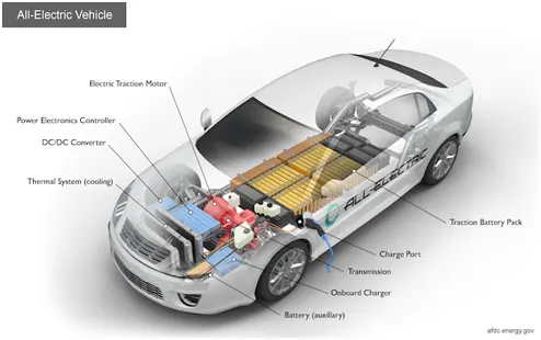
AC-DC Converter is a device that converts an AC voltage to DC voltage. This Converter in electric and hybrid electric vehicle also called On Board Charger AC to DC converters is most commonly used in Plug-in Hybrid Electric Vehicles (PHEV) & Plug-in Electric Vehicles (PEV).
DC – DC Converter
Converts fixed dc input voltage to a controlled dc voltage. The batteries of an electric vehicle typically output several hundred volts of DC. The electric components inside the vehicle vary in their voltage requirements, with most running on a much lower voltage. This includes the radio, dashboard readouts, air conditioning, and in-built computers and displays. In electric vehicles which use a DC motor, actually running the motor can use up to three times the voltage provided by the battery. A simplified step-down converter work by generating a series of on-off pulses, and then using a combination of inductors and capacitors to smoothen this into a consistent DC signal, whose current is constant and whose voltage is determined by the duty cycle (that’s the duration of on states relative to off ones).
DC – AC Converter (Inverter):
An inverter is a device that converts DC power to the AC power used in an electric vehicle motor. The inverter can change the speed at which the motor rotates by adjusting the frequency of the alternating current. It can also increase or decrease the power or torque of the motor by adjusting the amplitude of the signal.
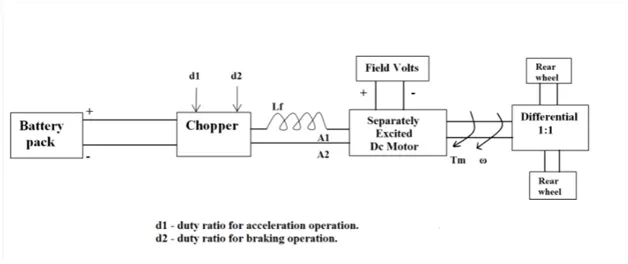
2.An Electric Vehicle's power train with 72V battery pack in shown in the diagram below. The duty ratio for acceleration operation is 'd1' and for the braking operation the duty ratio is 'd2'.
Motor and Controller Parameters
Rated Armature voltage= 72 V
Rated armature current= 400 A
Ra= 0.5Ω, KΦ= 0.7 Volt second
Chopper Switching frequency= 400 Hz
Duty cycle = 70%
= 70/100
= 0.7
The vehicle speed-torque characteristics are given by
Tv = 24.7 + (0.0051)ω2 --------------- Eqn 1
We know that,
Torque (T) = Vkɸ/Ra-[(kɸ)2/Ra]ω
Voltage = 72*duty cycle
= 72*0.7
= 50.4volts
Torque (T) = 50.4(0.7)/0.5 – [(0.7)(0.7)/0.5]ω
T = 70.56 – 0.98 ω ------------------------ Eqn2
Equating equation 1 & 2
24.7 + (0.0051)ω2 = 70.56 – 0.98ω
0.0051 ω2 + 0.98 ω – 45.86 = 0
After solving above quadratic equation the roots are
ω = 38.91498268 & ω = −231.07184542
Therefore the EV steady state speed of the motor with duty cycle of 70% is ω = 38.91 rad/sec.
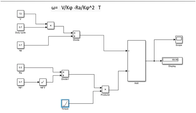
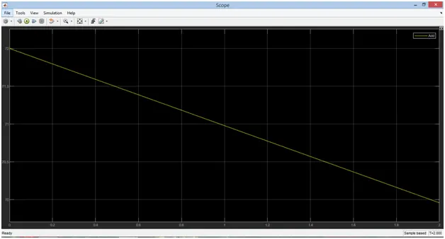
3.Mathematical model of a DC Motor for the below equation using Simulink
ω= V/Kϕ -Ra/Kϕ^2 T
4.Induction Versus DC brushless motors by Wally Rippel, Tesla
As per the Author Perspective firstly he starts with the vehicle engines with a tag of “ONE SIZE DOES NOT FIT ALL”. The vehicle engines are differ from one vehicle to another the author thinks that there is no best engine suits requirements such as price and performance. The author describes about the future for lithium batteries, DC brushless motors and Induction motors.
As we all know that the DC brushless motor has a Stator and Rotor. These two components are important to any machine. The rotor includes two or more permanent magnets that generate a magnet field around it. This magnet field enters the stator core interacts with current flowing within the windings to produce the torque between the rotor and stator. When the rotor starts rotates the necessary magnitude and polarity of the stator currents be continuously varied then torque remains constant.
The stator of the 3-ɸ induction motor and DC brushless motor are similar. The main difference between two machines is with the rotor. Unlike the DC brushless rotor, the induction rotor has no magnets stacked steel laminations with Currents flowing in the stator windings produce a rotating magnetic field that enters the rotor. The frequency of this magnetic field by the rotor is equal to the difference between the applied electrical frequency and the rotational frequency of the rotor itself. When a 3-phase induction motor is connected to 3-ɸ power, the motor requires high starting torque under load condition. A brushless DC motor produces no starting torque when directly connected to fixed frequency utility power. Both DC brushless and induction drives use motors having similar stators. Both drives use 3-phase modulating inverters. The only differences are the rotors and the inverter controls. And with digital controllers, the only control differences are with control code. DC brushless drives require an absolute position sensor, while induction drives require only a speed sensor; these differences are relatively small. When maximum torque is required, especially at low speeds, the magnetic field strength should be maximum so that inverter and motor currents are maintained at their lowest possible values. This minimizes the I² R losses. When torque is low, the B field should be reduced such that eddy and hysteresis losses due to B are also reduced. Ideally, B should be adjusted such that the sum of the eddy, hysteresis, and I² losses is minimized. The author clearly explain about how the magnetic field will works when the speed is low and high . The advantage with DC brushless as machine size grows the magnetic losses increase proportionately and load efficiency drops. With induction, as machine size grows, losses do not necessarily grow. Thus, induction drives may be the favored approach where high-performance is desired peak efficiency.
Finally the author concludes DC brushless drives will likely continue to dominate in the hybrid and coming plug-in hybrid markets, and that induction drives will likely maintain dominance for the high-performance pure electrics.