Week-6 Challenge: EV Drivetrain
AIM:
- To understand different power convertors found in EV vehicles.
- To understand duty cycle ratio and Power electronics on he vehicle control
- To design a mathematical model of a DC Motor using Simulink.
- Author perpective on Induction motor vs DC brushless motors by Walley Rippel.
OBJECTIVE 1: Which types of power converter circuits are employed in electric and hybrid electric vehicle?
There are 4 main categories of Power converter which are elaborated below:
AC to DC Converter (Controlled Rectifier)
An AC to DC converter circuit can convert AC voltage into a DC voltage. The DC output voltage can be controlled by varying the firing angle of the thyristors. The AC input voltage could be a single phase or three phase.
AC to AC Converters. AC to AC Converter
This converters can convert from a fixed ac input voltage into variable AC output voltage. The output voltage is controlled by varying firing angle of TRIAC. These type converters are known as AC voltage regulator.
AC to AC converters known as frequency shifters doesn't find much application in electric vehicles.
DC to DC Converters
These converters can converter a fixed DC input voltage into variable DC voltage or vice versa. The DC output voltage is controlled by varying of duty cycle. These are known as chopper.
DC to AC Converters or Inverters
These converters are connected between DC source of fixed input, and variable AC load. Most commonly, these DC to AC converters are called as inverters. An inverter is a static device that converts fixed DC supply voltage to variable AC voltage.
OBJECTIVE 2:
For dc machine Torque- Speed relation
where V= volatage supply
Km(ϕ">ϕ)= Motor constant
Ra = armature resistance
ω">ω= angular speed of motor
Voltage(motor) = Voltage of armature * dutycycle
= 72*0.7
=50.4volts
T=50.4⋅(0.7/0.5)-ω⋅(0.7^2/0.5)
T= 70.56-0.98*ω .......................... (1)
Tr= 24.7 + 0.0051*ω^2.....................(2)
Equating 1 and 2
70.56-0.98ω = 24.7 + 0.0051*ω^2
ω2+192.151⋅ω-8992.156=0
ω=38.91rad/sec
Objective3.
ω= V/Kϕ -(Ra/Kϕ^2).T
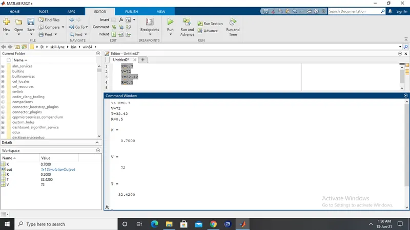
assuming the values as -
V=72v
Kϕ = 0.7
Ra= 0.5 ohm
T= 32.42 N-m
following simulink model was made-
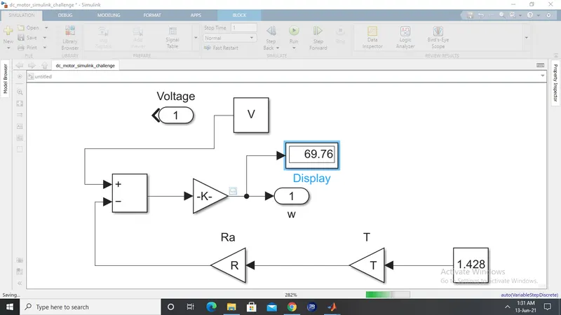
w came out to be 69.76 rad/sec.
OBJECTIVE 4 : Induction motor vs DC brushless motor by Wally Rippel
Author Wally Rippel starts with a reflection on the old times when there were lead acid batteries,contact controllers,etc. which have lost their significance now as the motors and their control have evolved in recent times.Technology has advanced a lot in these passed decades but he is sure that the brushless DC motor (BLDC) and the Induction motor is here for a long haul.
Then he starts with a closer look on the two types;strarting with BLDC motor. Structure is explained and stress on the inverter is given for the functioning of the motor.
Then coming to Induction motor he points out that the major difference lies in the rotor of the two motors as unlike DC brushless rotor,Induction rotor has no permanent magnets.
The fact that Induction motors are directly compatible with conventional utility power is the main reason for their success. In contrast,BLDC motor produces no starting torque when directly connected to fixed frequency utility power.
Induction motors have some limitations too as they can only operate on AC supply voltage.When used with utility power they are constant speed machines. Torque performance is low compared to BLDC motor.
Less heat in rotor of BLDC is present. control differences are with the control code only.In Induction motors Eddy and Hysteresis losses can be minimised whereas due to permanent magnet in BLDC there is no such option.
Induction motors have a cost advantage over BLDC. control is costly of Induction motor but then there is no recurring cost.
In the end author concludes with the remark that both are going to sustain as the hardware is common for both.He definitely points out that the AC Induction motors are going to find more use in high-performance pure electric vehicles whereas in plug-in hybrids and HEV are going to make use of BLDC motors.