Week-7 Challenge: DC Motor Control
Ans1.A:
In the MATLAB/SIMULINK documentation, we can search for the simulation model of the 'Speed control of a DC Motor using BJT H-bridge'. It is used to generate a chopped voltage and to control the speed of the DC motor. This model can be opened in SIMULINK from the documentation itself. As the name suggests, it uses a BJT (Bipolar Junction Transistor which is a type of transistor that uses both electrons and holes as charge carriers, hence the name bipolar. Other transistors such as FETs (Field Effect Transistors) are unipolar transistors meaning that they only use one type of charge carrier. BJTs are used for switching and amplifying applications.
BJTs have 3 terminals which are: the emitter (E), the base (B) and the collector (C). Current flows in only the emitter and the collector and the amount of current that flows through them is controlled by the base. BJTs use semiconductors in their working, and so there are 2 types of BJT: NPN type and PNP type.
PNP Transistor
This type uses 2 p-type semiconductors and one n-type semiconductor. The n-type semiconductor will be the base of the transistor. The emitter terminal is more positive in relation to the collector and base terminals. The collector is connected to positive supply and emitter is connected to negative supply. The base terminal is supplied with voltage and it operates the transistor by switching between ON or OFF states. When the base voltage is the same as the emitter voltage, the transistor is in the OFF state. When the base voltage decreases with respect to the emitter voltage, the transistor is in the ON state.
NPN Transistor
This type uses 2 n-type semiconductors and one p-type semiconductor. The p-type semiconductor will be the base of the transistor. Construction wise it is exactly the same as the PNP type having 3 terminals. Just as in the PNP type, the collector terminal is conneced to the positive voltage supply and the emitter terminal is connected to the negative voltage supply. The base terminal is supplied with a voltage and controls the transistor being either in an ON or OFF state. When the base voltage is the same as the emitter voltage, the transistor will be in the OFF state. When the base voltage increases with respect to the emitter voltage, the transistor will be in the ON state.
BJT H-Bridge
When the BJT is conducting i.e. operating in the saturated region, there will be a forward voltage developed between the collector and the emitter (in the range of 1V). An IGBT is used to model the BJT because of this. The switch is controlled by a SIMULINK signal. The DC motor used in this model is preset to with specifications: 5HP, 24V, 1750rpm. It simulates a fan type load where the load is proportional to the square of the speed. The mean armature voltage can be varied between 0 and 240V when the duty cycle is changed anywhere from 0 to 100%. The duty cycle can be changed from the pulse generator block.
The H-bridge consists of 4 BJT and Diode pairs. Two transistors are switched on simultaneously: Q1 and Q4 or Q2 and Q3. When Q1 and Q4 are fired, a positive voltage is applied to the motor and the diodes, D2 and D3 operate as free wheeling diodes when Q1 and Q4 are switched off. Similarly, when Q2 and Q3 are fired, a negative voltage is applied to the motor and the diodes, D1 and D4 operate as free wheeling diodes when Q2 and Q3 are switched off.
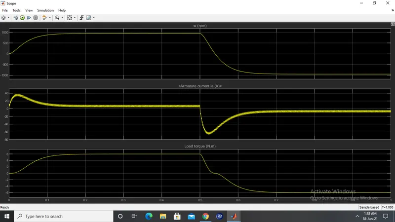
By default, the motor will start in the positive direction and has a preset duty cycle of 75% with a mean DC voltage of 180V. At t = 0.5 seconds, the armature voltage will reverse and the motor will run in the negative direction.
This is the SIMULINK model for the BJT H-Bridge used in the speed control of a DC motor:
The image below shows the output of the scope when the simulation is run using the preset values in the pulse generator block. There are 3 output graphs of angular speed, armature current and the load torque all against a time axis.
scope results
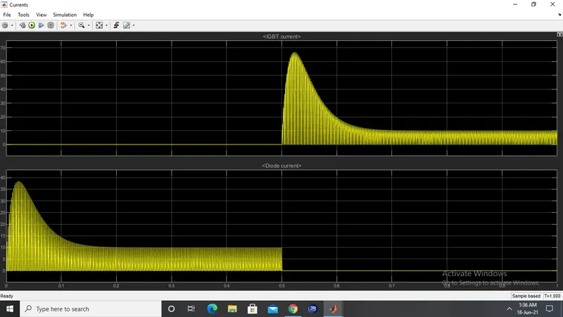
igbt current and diode current.
Ans1.B :
This shootup occurs whenever the armature voltage reverses direction which is every 0.5 seconds. In the second graph above (which shows the armature current vs. time) we can see that at the start of the cycle, there is a sharp increase in the armature current that then decreases and comes to a more stable level where it remains until 0.5 seconds. When the next cycle begins, the exact same effect occurs but in the negative axis because in this cycle, the armature voltage is reversed.
This frequency of reversing the voltage direction has been preset in the 'armature voltage control' block. Reducing the duty cycle will help in this.
Motor equation is :-
V= E(b) + I(a)R(a).
When we start the motor, there is no back emf to oppose the armature current because the conductors have not yet started rotating. Back emf is produced only when there is relative motion between conductors and magnetic field. When starting the motor, there is no relative motion so no back emf.
ANS 1.C :
The four quadrant chopper DC drive block in MATLAB/SIMULINK represents a four quadrant, DC supplied chopper drive for DC motors. It is also referred to as the 'DC7' motor drive in SIMSCAPE. It features closed loop speed control with four quadrant operation. The closed loop speed control will output the armature current of the machine. Using a PI current controller, the chopper duty cycle corresponding to the commanded armature current is derived. The duty cycle is then compared with a sawtooth carrier signal to obtain the required PWM signals for the chopper.
Compared to other DC drives, the main advantage of using the four quadrant chopper DC drive is that it can operate in all 4 quadrants. Each quadrant in its characteristics represents a different mode of operation. The first quadrant is forward motoring, the second is reverse braking, the third is reverse motoring and the forth is forward braking. Another advantage is that it uses high switching frequency DC-DC converters resulting in a lower armature current ripple is occurs than compared to thyristor based DC drives.
The 200 HP DC motor is separately excited with a constant 150 V DC field voltage source. The armature voltage is provided by an IGBT converter controlled by two PI regulators. The converter is fed by a 515 V DC bus obtained by rectification of a 380 V AC 50 Hz voltage source. In order to limit the DC bus voltage during dynamic braking mode, a braking chopper has been added between the diode rectifier and the DC7 block.
The first regulator is a speed regulator, followed by a current regulator. The speed regulator outputs the armature current reference (in p.u.) used by the current controller in order to obtain the electromagnetic torque needed to reach the desired speed. The speed reference change rate follows acceleration and deceleration ramps in order to avoid sudden reference changes that could cause armature over-current and destabilize the system. The current regulator controls the armature current by computing the appropriate duty ratios of the 5 kHz pulses of the four IGBT devices (Pulse Width Modulation). For proper system behaviour, the instantaneous pulse values of IGBT devices 1 and 4 are opposite to those of IGBT devices 2 and 3. This generates the average armature voltage needed to obtain the desired armature current. In order to limit the amplitude of the current oscillations, a smoothing inductance is placed in series with the armature circuit.
The four quadrant chopper DC drive uses these 4 main blocks from the fundamental drive blocks library:
- speed controller
- current controller
- regulation switch
- chopper
Comparison to H-Bridge
Both BJT H-bridges and 4 quadrant choppers have their advantages and disadvantages. H-Bridges like the 4 quadrant choppers are also capable of the braking operation without using air resistance or friction or physical brakes to bring the motor to rest. 4 quadrant DC choppers are more commonly used in automobiles whereas BJT H-bridges are commonly used in robotics and electro-mechanical devices.
Unlike 4 quadrant DC choppers, BJT H-bridges are not capable of performing regenerative braking but they can perform dynamic braking. It is this difference that makes 4 quadrant DC choppers useful in hybrid and electric vehicles.
In 4 quadrant DC choppers, the current signals are interrupted with one another to change the direction of rotation of the motor. This is done by a speed reference or a drive cycle from which the speed values are converted to current signals which interrupt one another to change the rotation of direction of the motor. However in BJT H-bridges, the polarity of the current is reversed (depending on the duty cycle) to change the direction of rotation of the motor.
Also, the current signals in 4 quadrant DC choppers are chopped meaning that they are not continuous, they are discrete and so take less time for simulations. But in BJT H-bridges, the current values are not chopped, meaning that they are continuous and so take more time for simulations.
Finally, in 4 quadrant DC choppers, a PI controller is used to control the speed and the current and in the H-bridge, this is not implemented.
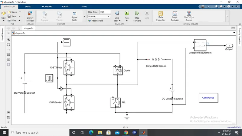
Ans2. Following simulink model was made:
Two-Quadrant Chopper (type C)
In this type of Chopper, the average voltage will be always positive but the average load current might be positive or negative. The two Switches CH1 and CH2 should not be turned on simultaneously as the combined action may cause a short circuit in supply lines. For regenerative braking and motoring these type of chopper configuration is used.
We will always get a positive output voltage V0 as the freewheeling diode FD is present across the load. When the chopper CH1 is on the current flows from source to load. The inductor stores energy. When Ch1 turn OFF the freewheeling diode starts conducting and the output voltage v0 will be equal to Vs. The direction of the load current i0 will be reversed. The current i0 will be flowing towards the source. The load current will be negative when the CH2 is on. The current completes its path through diode D2.
In the model sample time was kept for 0.05sec. Pulse given to the gate through pulse generator had an amplitude of 1,period of 0.001s and pulse width of 50%
The output obtained from the model is following:
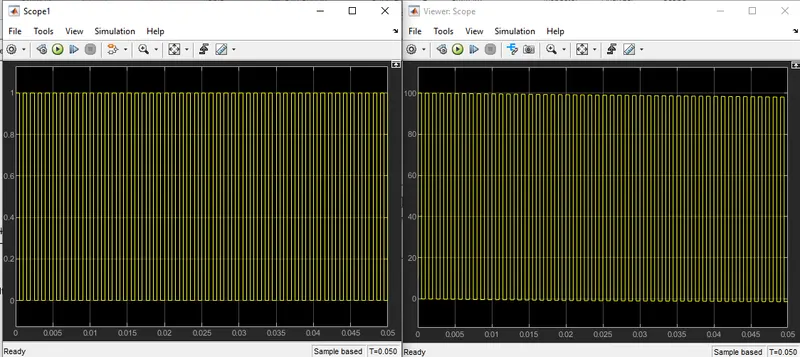
scope1 shows the gate signal given and Scope shows the voltage output that we get. It can be seen that the voltage remains positive throughout.
Simulink model file of the 2-quadrant chopper is attached.
Ans 3.
A brushless DC motor (also known as a BLDC motor or BL motor) is an electronically commuted DC Motor which does not have brushes. The controller provides pulses of current to the motor windings which control the speed and torque of the synchronous motor.
These types of motors are highly efficient in producing a large amount of torque over a vast speed range. In brushless motors, permanent magnets rotate around a fixed armature and overcome the problem of connecting current to the armature. Commutation with electronics has a large scope of capabilities and flexibility. They are known for smooth operation and holding torque when stationary.
Before explaining the working of a brushless DC motor, it is better to understand the function of a brushed motor. In brushes motors, there are permanent magnets on the outside and a spinning armature which contains electromagnet is inside. These electromagnets create a magnetic field in the armature when the power is switched on and help to rotate the armature.
The brushes change the polarity of the pole to keep the rotation on of the armature. The basic working principle for the brushed DC motor and for brushless DC motor are same i.e. internal shaft position feedback.
Brushless DC motor has only two basic parts: rotor and the stator. The rotor is the rotating part and has rotor magnets whereas stator is the stationary part and contains stator windings. In BLDC permanent magnets are attached in the rotor and move the electromagnets to the stator. The high power transistors are used to activate electromagnets for the shaft turns. The controller performs power distribution by using a solid-state circuit.
Advantages of Brushless DC Motor
The advantages of a BLDC motor are:
- Brushless motors are more efficient as its velocity is determined by the frequency at which current is supplied, not the voltage.
- As brushes are absent, the mechanical energy loss due to friction is less which enhanced efficiency.
- BLDC motor can operate at high-speed under any condition.
- There is no sparking and much less noise during operation.
- More electromagnets could be used on the stator for more precise control.
- BLDC motors accelerate and decelerate easily as they are having low rotor inertia.
- BLDC motors do not have brushes which make it more reliable, high life expectancies, and maintenance free operation.