Project-1: Powertrain for aircraft in runways
Part A:
Ans1.
Airbus
{ A300, A310, A318, A319, A320,
A321, A330, A340, A350, A380}
- weight = 500 to 600 tonnes
Boeing
{ B737, B747, B747-8,
B757, B767, B777, B787}
- weight = 200 to 300 tonnes
Single-Engine Piston
- weight = 5 to 10 tonnes
Business Jets
- Weight = 7 to 15 tonnes
Taildraggers
- weight = 5 to 10 tonnes
Helicopters
- weight = 5 to 22 tonnes
Floatplanes or Seaplanes
- weight = 5 to 10 tonnes
Ans2.
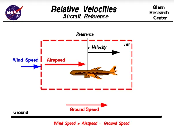
"Ground speed is the velocity of the plane relative to a reference point on the ground. Wind speed is the velocity of wind concerning that same reference point, and airspeed is the velocity of the plane relative to that wind. Thus the airspeed is defined as the vector difference between the ground speed and the wind speed. Also note that for whatever reason, the three quantities have both direction and magnitude; they are vectors despite their names".
Ans3.
Although most aircraft are capable of moving themselves on the ground, it is not typically done due to the following reasons,
- The jet blast from the engines can damage the terminal building and nearby equipment. It can even throw away people standing nearby.
- Engines can blow sand and debris.
- Engines can suck in sand and debris which can cause serious damage to the engine.
- It is easier for the truck driver to see the surroundings better than the pilot sitting in the cockpit with limited windows.
- The plane engines are very loud. This noise can add up substantially when multiple planes are moving around the airport. It won't be a pleasant experience for people sitting inside the terminal, as most people don't even like the sound of powerful motor-bikes.
- It saves fuel.
- Modern planes are huge. It is difficult to navigate such gigantic structures through limited space. An A380 is eight stories high. The pilots won't be able to see anything directly in front of them or anything behind the wings.
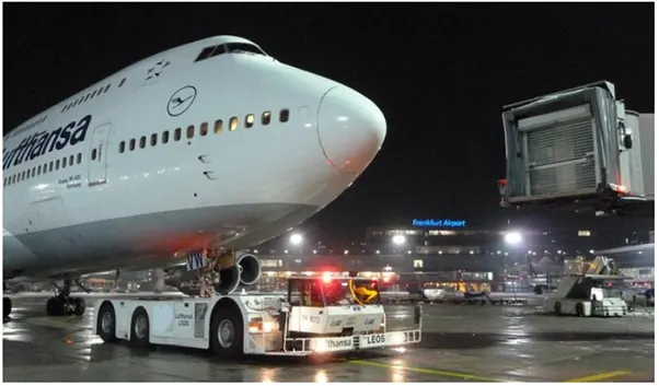
Ans4. Aircraft are usually ‘pushed’ by ground vehicles known as tow vehicles such as tow trucks. It is used mainly to reverse an aeroplane from the terminal area until it is in a position to move by itself. These tow trucks will only help move the aircraft to an area where the pilots can safely switch on the engines, not the runway! (Ground vehicles are rarely allowed to move on a runway and the aircraft is supposed to move to the runway by itself.
Aircraft don’t have powered wheels, and hence cannot move in reverse (let alone forward by themselves). Imagine a tiny jet strapped to one of your toy cars; that’s essentially how aeroplanes work on the ground! They go where the engines push them towards.
Ans5.
Takeoff
It is the phase of flight in which an aircraft goes through a transition from moving along the ground (taxiing) to flying in the air, usually starting on a runway. Take off power can be predicted using a simple measure of the acceleration of the aircraft along the runway based on force equilibrium.
The forces involved will be,
T → Thrust of propulsion system pushing aircraft along the runway.
D → Aerodynamic Drag of vehicle resisting the aircraft motion.
F → Rolling resistance friction due to the contact of wheels or skids on the ground.
During the take-off run, the imbalance in these forces will produce an acceleration along the runway.
m*(dv/dt)=T-D-F
where, dv/dt is the acceleration along the runway and m is the mass of the vehicle.
The procedure for take-off will be that the vehicle will accelerate until it reaches a safe initial flying speed. The pilot can then rotate the vehicle to an attitude to produce a climb lift and it will ascend from the ground. The determination of this safe flying speed or rotation speed, Vr is a critical factor in determining take-off performance. Take-off rules vary slightly depending on the aircraft category.
For Small commuter aircraft
Vr=1.1×VSTALL
or
Vr=1.05×VControl
whichever is great.
`VSTALL = sqrt (W/(0.5* CLmax ⋅ ρ ⋅ S)`,
where S →displacement
Takeoff Field Length
The required length of the runway will be the sum of the distance required to get to rotation speed and the extra length required to clear a 50ft obstacle or the extra length required to allow for rapid braking if the pilot decides to abort take-off at the decision speed V1.
This length will typically be considerably longer than the distance required to achieve rotation (flying) speed. A rough approximation is that the runway total length is around S1=2.
Therefore,
Takeoff power = force * displacement
= (m⋅dv/dt)⋅2⋅S1=(T-D-F)⋅S1
Rolling Resistance
The friction between aircraft and runway will be proportional to the normal force exerted by the aircraft on the runway.
F=μ(W−L)
The normal force will be the difference between the Weight of the aircraft and the Lift, the friction coefficient will be typical of a magnitude of 0.02 for a standard runway
Braking Forces in Landing
The landing run can be calculated similarly to the take-off distance. The aim is again to minimise the distance.
The touchdown velocity should be approximately the stall speed of the aircraft in the landing configuration. This will be achieved by a pitch manoeuvre during the flare portion of the approach which increases drag and decelerates the aircraft to minimum flying speed. The deceleration on the landing roll from VTD to V0 will be accomplished by braking and reverse thrust. This can be solved by the average acceleration approach that was used to estimate the take-off roll.
m⋅(dv/dt)= -T-D-F
The negative acceleration or deceleration value will be based on the friction coefficient for maximum braking and the value of reverse thrust.
Aircraft Tyre design
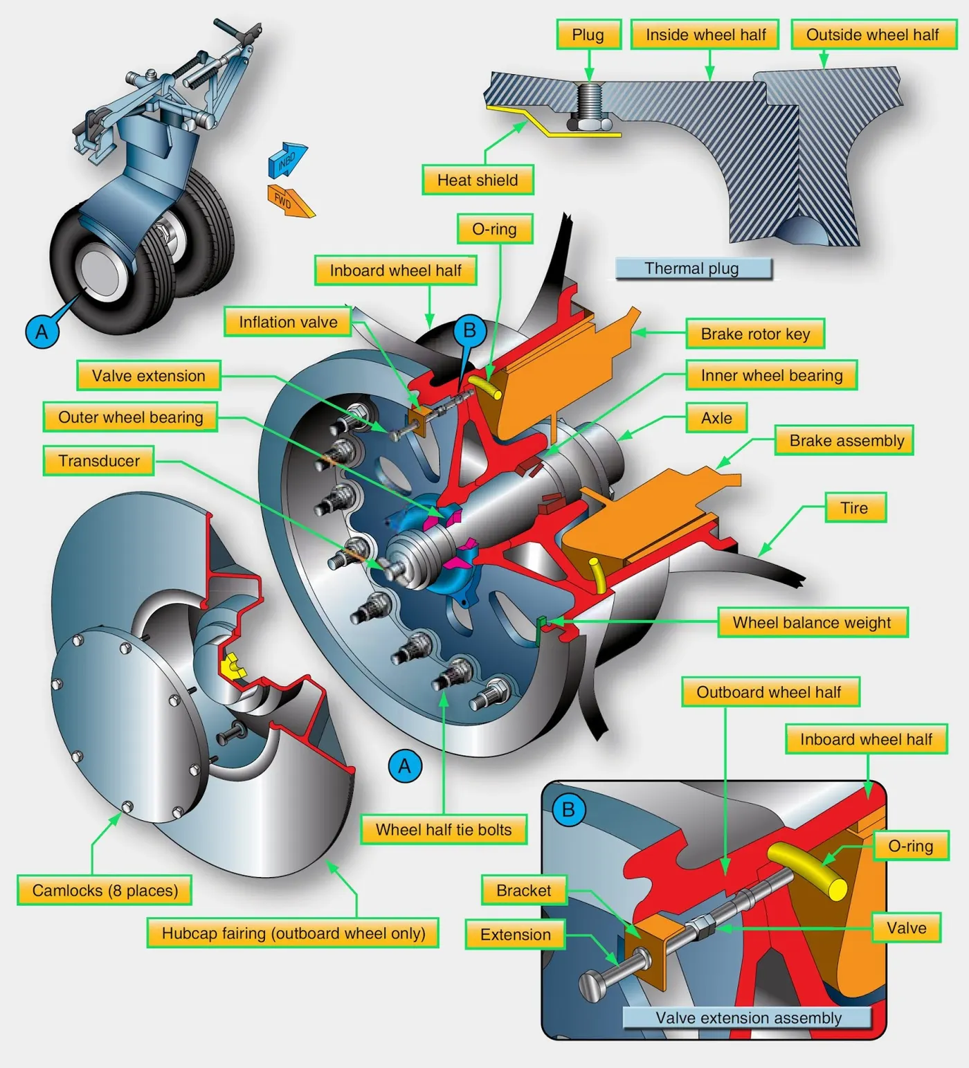
Aircraft wheels are an important component of a landing gear system. With tires mounted upon them, they support the entire weight of the aircraft during taxi, takeoff, and landing. The typical aircraft wheel is lightweight, strong, and made from aluminium alloy. Some magnesium alloy wheels also exist. Early aircraft wheels were of single-piece construction, much the same as the modern automobile wheel.
As aircraft tires were improved for the purpose they serve, they were made stiffer to better absorb the forces of landing without blowing out or separating from the rim. Stretching such a tire over a single piece wheel rim was not possible. A two-piece wheel was developed.
Early two-piece aircraft wheels were essentially one-piece wheels with a removable rim to allow mounting access for the tire. These are still found on older aircraft. Later, wheels with two nearly symmetrical halves were developed. Nearly all modern aircraft wheels are of this two-piece construction
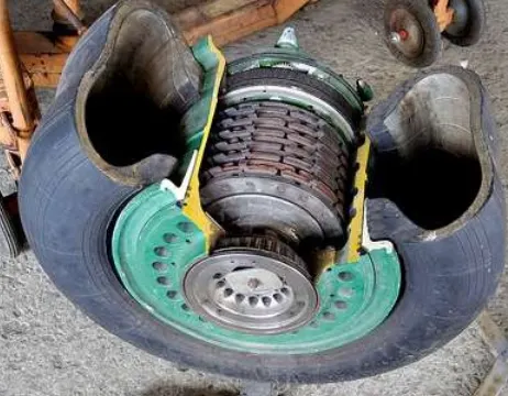
two-piece aircraft wheel found on a modern airliner
The typical modern two-piece aircraft wheel is cast or forged from aluminium or magnesium alloy. The halves are bolted together and contain a groove at the mating surface for an o-ring, which seals the rim since most modern aircraft utilize tubeless tires. The bead seat area of a wheel is where the tire actually contacts the wheel. It is the critical area that accepts the significant tensile loads from the tire during landing. To strengthen this area during manufacturing, the bead seat area is typically rolled to pre-stress it with a compressive stress load. Modern tyres are much more rigid, due to the load-bearing requirements, which results in the wheels having to be of two-piece construction.
Aircraft Tyre Pressure
Aircraft tyres generally operate at high pressures, up to 200 psi (14 bar or 1,400 kPa) for airliners, and even higher for business jets. The main landing gear was typically inflated to 232 psi (16.0 bar), whilst its tail bumper gear tires were as high as 294 psi (20.3 bar). The high pressure and weight load tyres were a significant factor.
Tests of airliner aircraft tyres have shown that they can sustain pressures of a maximum of 800 psi (55 bar; 5,500 kPa) before bursting. During the tests, the tyres have to be filled with water, to prevent the test room from being blown apart by the energy that would be released by gas when the tyre bursts.
Aircraft tyres are usually inflated with nitrogen to minimize expansion and contraction from extreme changes in ambient temperature and pressure experienced during flight. Dry nitrogen expands at the same rate as other dry atmospheric gases (normal air is about 80% nitrogen), but common compressed air sources may contain moisture, which increases the expansion rate with temperature.
The requirement that an inert gas, such as nitrogen, be used instead of air for inflation of tyres on certain transport category aeroplanes was prompted by at least three cases in which the oxygen in air-filled tires had combined with volatile gases given off by a severely overheated tire and exploded upon reaching autoignition temperature. The use of inert gas for tyre inflation eliminates the possibility of a tyre explosion.
PART B.
Ans6.A.
Traction Force
The force propelling the vehicle forward, transmitted to the ground through the drive wheels.
Let’s assume
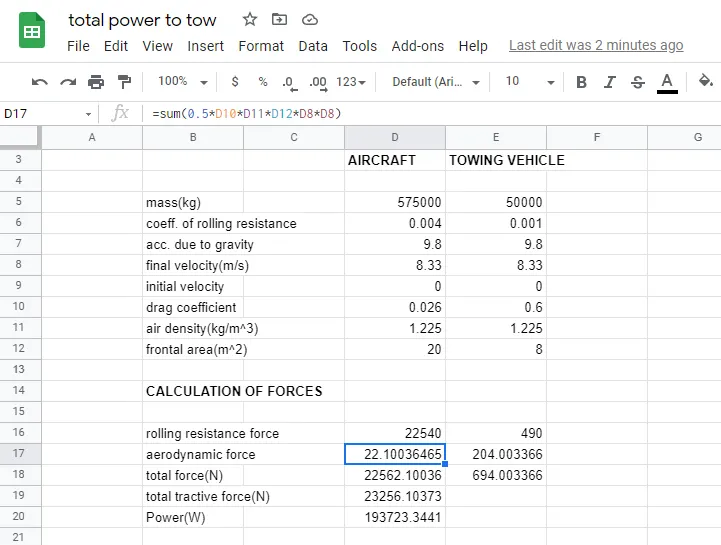
Weight of the Aircraft (Airbus A-380) = 575000 kg.
Rolling Resistance Coefficient of an Airbus (rr) = 0.004.
Weight of the towing tractor = 50000 Kg.
Rolling Resistance coefficient of the towing tractor (rr) = 0.001
Rolling Resistance force of the towing tractor = rr * m.g = 0.001*50000*9.81 = 0.49 KN.
Rolling Resistance force of an Aircraft = rr * m.g = 0.004*575000*9.81 = 22.56 KN.
Total Rolling Resistance Force = Rolling Resistance force of an Aircraft + Rolling Resistance force of the towing tractor
= 0.49 + 22.56
= 23.05 KN.
Air-Drag Force –
It is the force which occurs due to the Air Strike effect on the wheel when it moves. The vehicle moves through the air medium of particular density value with certain speed this causes the air strike against the vehicle body & it causes Drag force on the vehicle.
The Aerodynamic Drag is given by the following equation –
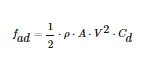
ρ= Density of the air medium.
A = Frontal area of the vehicle which strikes the vehicle.
V = Velocity with which the vehicle moves.
Cd = Coefficient of Drag which varies different shapes of the frontal area.
Let’s assume
The Velocity of the Aircraft while Towing = 30 Kmph. (8.33 m/s)
Density of Air medium (ρ) = 1.225.
The frontal area of the Aircraft = 20 m2.
The coefficient of the Drag of the Aircraft = 0.026.
Air Drag Force = 0.5*ρ*A*V2* Cd = 0.022 KN.
Air Drag Force of the Aircraft = 0.022 KN.
Air drag force of the towing vehicle
frontal area = 8m^2
coeff. of drag = 0.6
Air Drag Force = 0.5*ρ*A*V2* Cd= 0.5*1.225*8*8.33^2*0.6
=0.020KN
FT = Frr (a) + Fd (a) + Frr (t) + Fd (t)
FT = 22.56+0.022+0.49+0.020 (KN)
FT=23.092 KN
POWER REQUIRED TO PUSH OR PULL THE AIRCRAFT
P = FT * V
P= 23.092 × 8.33= 192.35636 KW
Ans6.B
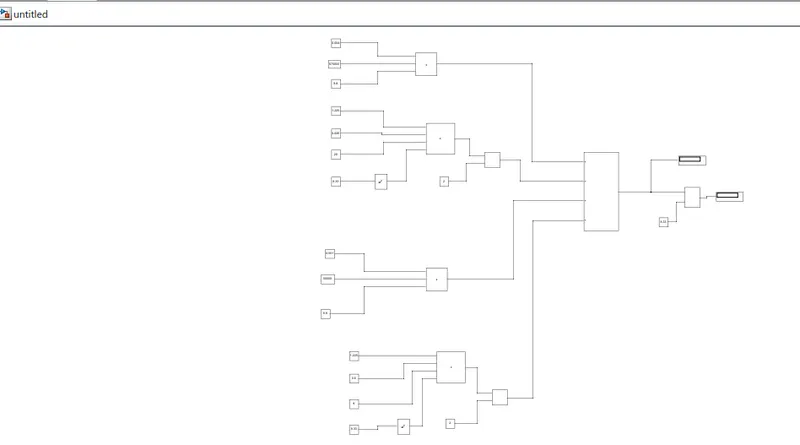
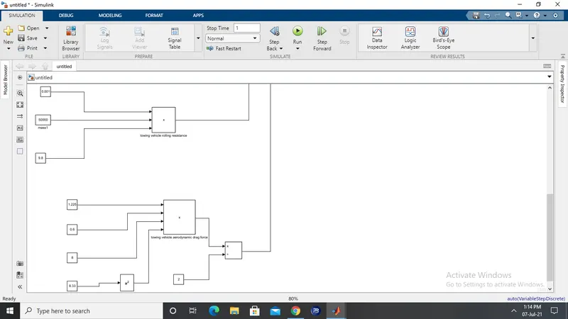
SIMULINK MODEL FOR CALCULATION OF FORCE AND POWER
EXPLANATION OF THE MODEL
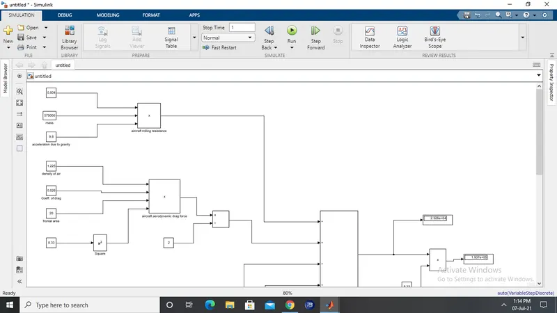
- From the above figure for the creation of the Simulink model, firstly we consider all the forces acting on the aircraft such as rolling resistance force, aerodynamic drag force.
- The values are assumed for mass of the aircraft, coefficient of rolling resistance, frontal area, drag coefficient and velocity and substituted in the respective formulas for rolling resistance force, drag coefficient force.
- Similarly for the above figure the forces are calculated for the towing vehicle the values are assumed and substituted in the respective formulas for rolling resistance force, aerodynamic drag force.
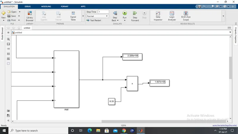
- Finally, all the forces are added to obtain the total tractive force and the power is obtained by multiplying the total tractive force with the velocity.
- The simulation is run and the both the force and the power values are displayed using the display block.
Ans7.A.
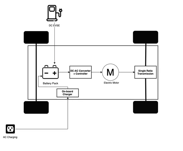
An EV powertrain has 60% less components than the powertrain of an ICE vehicle. These components are described below –
Battery Pack –
The Battery pack is made up of multiple lithium ion cells & stores the energy needed to run the vehicle. Battery pack provides the Direct current (DC) output.
DC-AC Converter –
The DC supplied by the battery pack is converted to AC & supplied to an electric motor. This power transfer is managed by sophisticated motor control mechanism (Referred as Powertrain Control Electronic Unit) that control the frequency & magnitude of voltage supplied to the electric motor in order to manage the speed & acceleration as per driver’s instructions communicated via acceleration/brakes.
Electric Motor –
Converts electrical energy to mechanical energy which is delivered to the wheels via single ratio transmission. Many EVs use motor generators that can perform regeneration as well.
On-Board Charger –
Converts AC received through charge port to DC & controls the amount of current flowing into the battery pack.
Core components of EV powertrain –
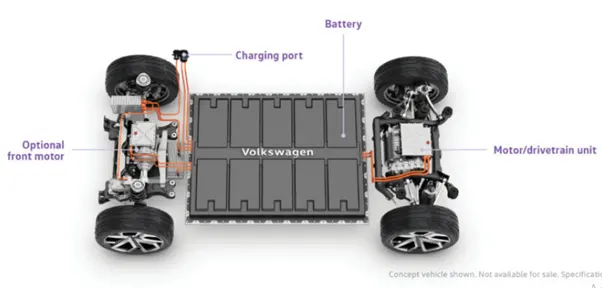
The following are the assumed parameters:
AIRCRAFT PARAMETERS
|
PARAMETERS |
VALUES |
UNITS |
|
Mass of the aircraft |
575000 |
kg |
|
Coefficient of rolling resistance |
0.004 |
-- |
|
Frontal area of the aircraft |
20 |
M2 |
|
Final velocity of the aircraft |
8.33 |
m/s |
|
Initial velocity of the aircraft |
0 |
m/s |
|
Coefficient of drag of an aircraft |
0.15 |
-- |
|
Acceleration time of the Towing vehicle |
10 |
Seconds |
TOWING VEHICLE PARAMETERS
|
PARAMETERS |
VALUES |
UNITS |
|
Mass of the Towing vehicle |
50000 |
kg |
|
Coefficient of rolling resistance |
0.001 |
-- |
|
Frontal area of the Towing vehicle |
8 |
M2 |
|
Final velocity of the Towing vehicle |
8.33 |
m/s |
|
Initial velocity of the Towing vehicle |
0 |
m/s |
|
Coefficient of drag of the Towing vehicle |
0.60 |
-- |
|
Acceleration of the Towing vehicle |
10 |
seconds |
|
Gear ratio |
10 |
The total power required to push or pull the aircraft by the towing vehicle is 192.35KW and the total tractive force is 23.25KN. To calculate the torque required by the Towing vehicle the following parameters are assumed as shown above:
T = Fr * r /G
T = 23256.1 * 0.4 / 10
T = 930.24 Nm
The torque required for towing the vehicle to push or pull the aircraft is 930.24 Nm
To design the electric power train of the towing vehicle a motor is selected based on its power rating and the battery required based on energy requirement and duty cycle range to control the aircraft speed from zero to highest.
MOTOR
The motor is selected with a power rating of 297.022KW and torque of 1293.63 Nm . TECO IE2 electric induction motor is selected which has a power output of 210 KW and torque at full load is 1420Nm that satisfies the power output and torque needed for the vehicle.
MOTOR SPECIFICATIONS
Output power –210 KW, 280 hp
Full load speed – 740 rpm
Full load Efficiency – 94.5%
Full load current – 210A
Full load Torque – 1420 Nm
Rated voltage – 1100V/50 Hz
DUTY CYCLE
The rated voltage is 1100V and the current is assumed to be 250A. So, the input power of the motor is calculated as product of voltage and current.
Pi = V * I
Pi = 1100 *210
Pi = 231000W
Pi = 231KW
To calculate the duty cycle we divide output power to input power
𝛿 = Po / Pi
𝛿 = 192.35 / 231
𝛿 = 0.833
𝛿 = 83%
ENERGY
To calculate the energy required from batteries or battery pack. The energy is obtained by multiplying the output power and time. Assuming the battery usage for 5 minutes is 300 seconds.
E = Po * t
E = 192.35 * 300
E = 57705kJ
So, the battery pack provides 57705 KJ of energy to the vehicle. Since the battery are rated in kilowatt hour (KWH). We have to convert KJ to KWH we divide it by 3600.
E = 57705/3600
E= 16.03KWH
So, the battery pack should provide at least 16.03 KWH to the vehicle.
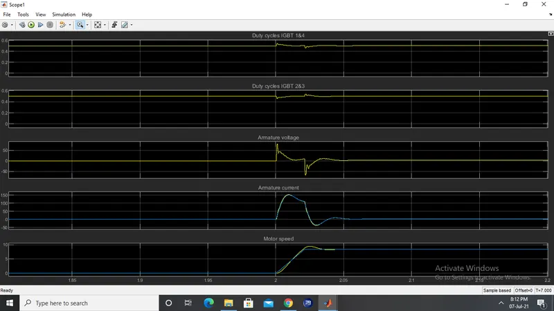
The velocity output can be seen as 8.33m/s.
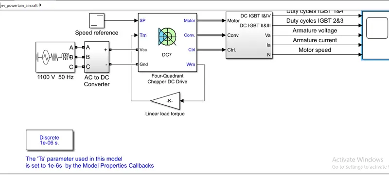
Ans7.B
File attached