Week-6 Challenge: EV Drivetrain
1.Which types of power converter circuits are employed in electric and hybrid electric vehicle?
Ans: Three diffrent types of power converter are used in electric and hybrid electric vechicle.
1: AC to DC converter
2: DC to AC converter
3: DC to DC converter
1.AC to DC Converter:
Batteries are most important component in EV vechicles.
Batteries store energy using DC supply. Generally availabe Power supply is AC. Therefore to convert AC to DC rectifier circuit is used.
Types of Rectifier circuit:
1. 1-phase and 3-phase Rectifier
2. Half bridge and Full bridge Rectifier.
3. Bridge Rectifier.
1-Phase full bridge Rectifier is generally used for electric and hybrid electric vechicle.
1-Phase full bridge Rectifier
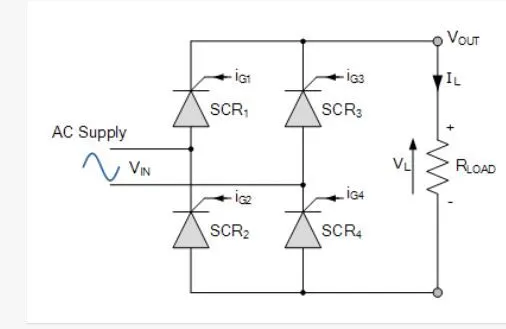
Input is AC Volatge is applied to above circuit. Based on SCR operations, we will get an output as DC average voltage.
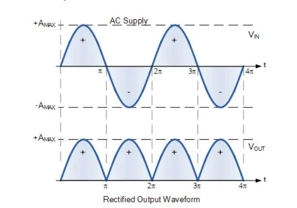
Above wave forms shows how and AC voltage supply is converted to DC average voltage.
Average voltage V0= (2*Vm*cos(alpha))/pi
2: DC to AC converter
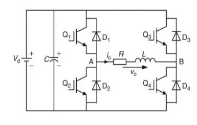
As batteries store energy in DC form . For AC motor it required AC supply. To convert DC power from batteries to AC supply for AC motor an Inverter circuit is used.
Types of Inverter circuits:
1: Half bridge and Full bridge Inverter.
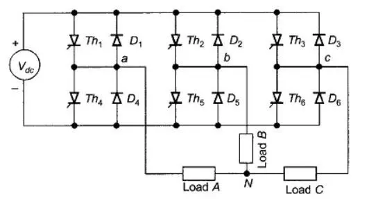
2: 3 phase : 180 mode and 120 mode inverter.
3: Multi level Inverter.
Based on type of Motor, diffrent types of inverters are used.
1. Full bridge Inverter
2. 3 phase : 180 mode and 120 mode inverter.
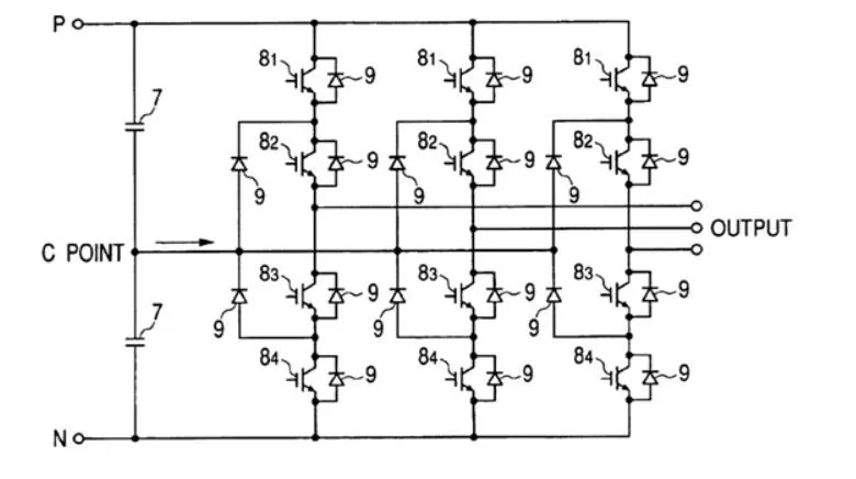
3: Multi level Inverter
To get pure Sinusoidal waveform at output , a multi level Inverters are used.
3: DC to DC converter.
As batteries store energy in DC form. For DC motor DC power is required. DC power available from batteries cant apply dircetly to DC motor. Here we need to use Chopper circuit for getting different voltage and current levels. Diffrent voltages are required for auxiliary supplies like speakers, Head lights, radio.
Types of DC choppers:
1: step down chopper or BUCK converter
2: Step up chopper or BOOst converter
3: Step up and down converter or Buck-Boost converter.
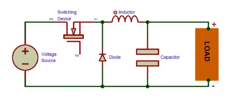
1: step down chopper or BUCK converter
It used to step down the voltage levels and increase the current levels for the Load.
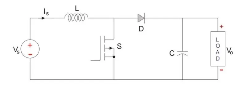
2: step up chopper or Boost converter
It used to step up the voltage levels and decrease the current levels for the Load.
3: step up down chopper orBuck-Boost converter
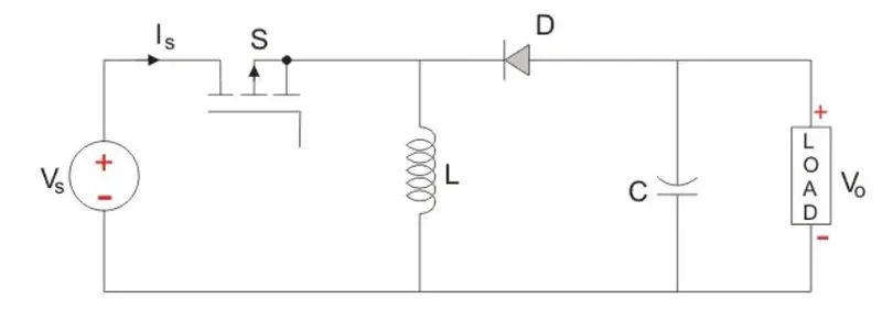
Based on duty ratio it will operate as buck or boost converter.
2. An Electric Vehicle's powertrain with 72V battery pack in shown in the diagram below. The duty ratio for acceleration operation is 'd1' and for the braking operation the duty ratio is 'd2'.
The other parameters of the electric vehicle is given below,
Motor and Controller Parameters:
Rated Armature voltage= 72 V
Rated armature current= 400 A
Ra= 0.5Ω, KΦ= 0.7 Volt second
Chopper Switching frequency= 400 Hz
The vehicle speed-torque characteristics are given by the below equation
 ...................1
What is EV steady state speed if duty cycle is 70%?
Ans:
Given data:
Battery voltage=72V
Aramature current= 400A
Armature Resistance = 0.5ohm
chopping frequency fs= 400hz
KΦ= 0.7 Volt second
Duty ratio =70%=70/100=0.7
output voltage from chopper
= 72*duty ratio
=72*0.7
=50.4V
this 50.4 voltage is applied to terminal of DC motor
we know that
w=(v/KΦ) -(R/(KΦ)^2) * T
Subjecting T keeping KΦ as it is
we get T=((v-KΦ*w)*KΦ)/R
subsitute the values we get
T=(50.4-0.7*w)*0.7/0.5
T=70.56-0.98w................2
comparing equation 1 and 2 we get
70.56-0.98w=24.7+0.0051w^2
0.0051*w^2+0.98*w-45.86=0
sloving above quadratic equation we get
w1=38.9 rad/sec w2= -231.07 rad/sec
taking speed as postive we get w= 38.9rad/sec.
3. Develop a mathematical model of a DC Motor for the below equation using Simulink.
ω">ωω= V/Kϕ">ϕϕ -Ra/Kϕ">ϕϕ^2 .T
Aim: To develop a mathematical model of a DC Motor using Matlan simulink.
Blocks Required for this Model:
1. Constant block
2. Adder and substractor
3. Mulitplier and divider
4.Scope
5.Display
Explanation:
w=(v/KΦ) -(R/(KΦ)^2) * T
where v= voltage
R=resistance
T= torque
Data assumed:
v=72V
R=0.5ohm
KΦ=0.7 volt sec
T=15Nm
Simulink diagram:
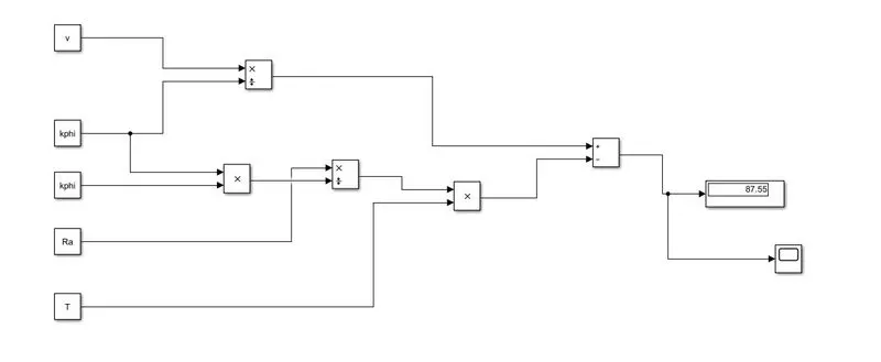
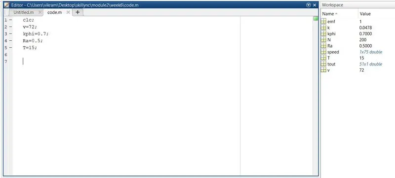
Values can be obtain from workspace
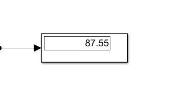
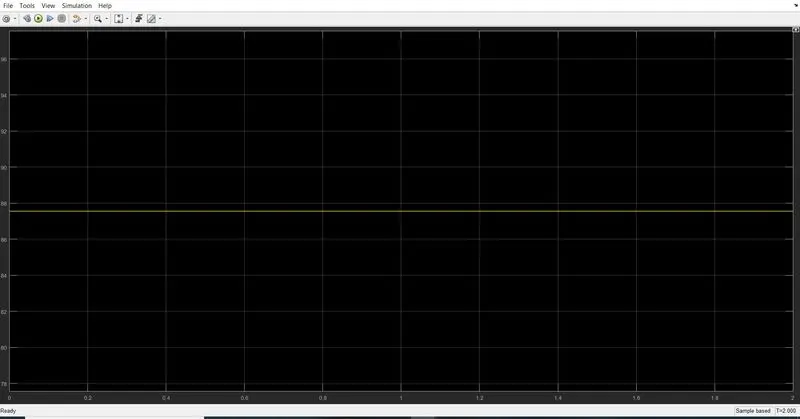
Result:
Procedure:
- Open Matlab simulink and create a new slx file.
- create a constant block and assaign a variable name.
- Date to variable can be obatain from work space. The values can be obtained to work space using matlab scrip file.
- Run the simulation and obtained the result.
Therotical values:
w=(v/KΦ) -(R/(KΦ)^2) * T
=(72/0.7)-(0.5/(0.7)^2)*15 =87.55
4. Refer to the blog on below topic:
Induction Versus DC brushless motors by Wally Rippel, Tesla
Explain in brief about author’s perspective.
Ans:
Author’s perspective: Everything will not get in single Machine. One has comprise one or more parameters based on requirement.
Author has compared BLDC motor with Induction motor.
1: Brushless DC motor is same as synchronous motor , but input is DC supply and its is converted to AC supply using Inverter.
2: Induced EMF is Trapazoidal waveform in stator winding.
3: Generally three switches are excited at a time in Inverter circuit. But In BLDC motor only 2 switches are excited In inverter circuit.
4: DC motor has good advantage compare to all motor especially in controlling speed , torque etc.But disadvantage in DC motor is Brushes.
5: These brushes are required regural Maintence. sparking may occur at this brushes.
6: To overcome above draw back, The Induction motor are come into picture.
7:Induction motor dont have brushes, having less maintence. These motors become popular compare to DC machines.
8: Induction has problem of starting current torque, speed control is not easy in these motors.
9:These motors have less torque compare to DC motors.
10: Inverters are invented in 1960. Then researches added this inverter to synchronous motor. Therefor a new motor was developed. They have named a motor has BLDC motor.
11: In this commutation is done using electronic switches and this motor has good torque characteristics comapre to induction motor.
12: These motor uses permanent magnets where as In induction motor electro magnets are generated by excitation.
13: Induction motors are directly compatible with conventional utility power is the main reason for their success. In contrast, a brushless DC motor produces no starting torque when directly connected to fixed frequency utility power. They really need the aid of an inverter whose “phase” is maintained in step with the angular position of the rotor.
14. Achieving stability over the entire torque-speed range and over temperature is more difficult with induction than with DC brushless. This means added development costs, but likely little or no recurring costs.
15. BLDC motors are costlier compare to Induction motors, but controlling speed, torque is very easy compare induction motor.