Week-6 Challenge: EV Drivetrain
1 Which type of power converter circuit are employed in electric and hybrid electric vehicles
The types of power converter circuits used in hybrid and electric vehicle are
RECTIFIERS - which transforms input ac supply to dc. the ev chargers are basically rectifiers.
INVERTERS - do converts power from one dc level to another ac voltage and frequencies.EV motor drives are Inverters.
CHOPPERS - transforms one level od dc to another level of dc.it can be stepup choppers and stepdown choppers used accordingly.the headlights in car require only 12v whereas the battery supply is 100v so stepdown choppers are used.
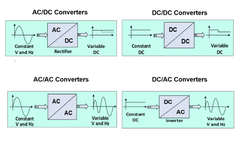
The different configurations of EV power supply show that at least one DC/DC converter is necessary to interface the FC, the Battery or the Supercapacitors module to the DC-link.
DC/DC converters can be designed to transfer power in only one direction, from the input to the output. However, almost all DC/DC converter topologies can be made bi-directional. A bi-directional converter can move power in either direction, which is useful in applications requiring regenerative braking.
The non-isolated converters type is generally used where the voltage needs to be stepped up or down by a relatively small ratio (less than 4:1). And when there is no problem with the output and input having no dielectric isolation.
There are five main types of converter in this non-isolated group, usually called the buck, boost, buck-boost, Cuk and charge-pump converters.
The buck converter is used for voltage step-down, while the boost converter is used for voltage step-up. The buck-boost and Cuk converters can be used for either step-down or step-up. The charge-pump converter is used for either voltage step-up or voltage inversion, but only in relatively low power applications.
Isolated converters, in this type of converters a high frequency transformer is used. In the applications where the output needs to be completely isolated from the input, an isolated converter is necessary. There are many types of converters in this group such as Half-Bridge, Full-Bridge, Fly-back, Forward and Push-Pull DC/DC converters. All of these converters can be used as bi-directional converters and the ratio of stepping down or stepping up the voltage is high.
2 To determine steadyspeed of EV with duty cycle 70%.
Q An electric vehicle's powertrain with 72V Batterypack in shown in the diagram below.
The duty ratio for acceleration operation is d1 and for the braking operation the duty ratio is d2
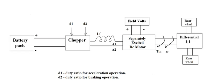
rated armature voltage Vb = 72v
rated armature current Ia = 400A
Ra = .5 ohm
kphi = .7voltsecond
chopper switching frequency = 400 Hz
motor voltage Vm = Vb *d
Vm = 72*.7 Vm =50.4V
the given equation foe torque is given as
Tv = 24.7+(.0051)`omega`^2` equatio(1)
by the dc motor torque equation
T = V*kphi/Ra - (kphi)^2/Ra * `omega`
T = 50.4*.7/.5 - .7^2/.5 * `omega`
T = 70.56-.98`omega` ...equation2
equating 1 and 2
24.7+.0051`omega`^2 = 70.56-.98`omega`
.0051`omega`^2+.98`omega`-45.86=0 divide both by .005`
`omega`^2+192.156`omega`-8992.156 = 0
by solving the quadratic equation roots the equations are
`omega`= 38.916 rad/sec or `omega`=-231.078 rad/sec
speed of EV = 38.91 rad/sec.
3 Develop a mathematical model of a DC motor for the below equation using simulink
w = v/kphi -Ra/kphi^2 .T
This is the mathematical model of dc motor for the equation
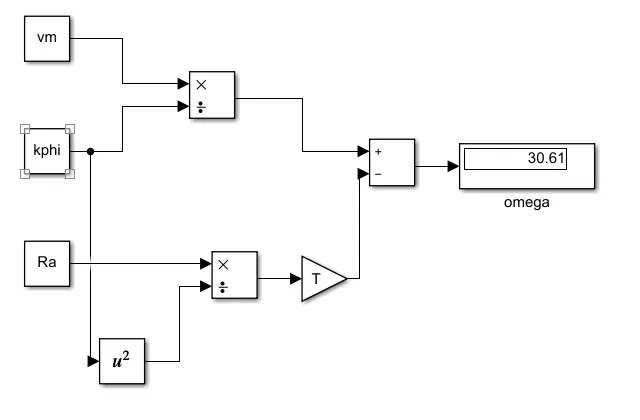
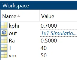
All the variables are substituted by values and given as per the equation for the output omega.
4 Induction motors versus DC brushless motors.
As per the author Wally Rippel clearly explains about the pros and cons of both dc brushless motors and induction motors.by reading the article I conclude that dc brushless motors and induction motors has its own benefits in different fields.so as per the requirement the motors can be selected.
COMPARISON
MR Wally describes the advantages and disadvantages of both motors
Both have three sets of distributed windings that are inserted within the stator core. The essential difference between the two machines is with the rotor. Unlike the DC brushless rotor, the induction rotor has no magnets.
3-phase induction motor is connected to utility type 3-phase power, torque is produced at the outset; the motor has the ability to start under load. No inverter is neededa brushless DC motor produces no starting torque when directly connected to fixed frequency utility power. They really need the aid of an inverter.
Despite of construction the price and perfomance are more important
DC brushless drive dissipates less rotor heat and are good at peak point energy efficiency however the permanent magnets flux density cannot be changed according to the requirements.
In case of induction motors the B can varied according to the requirements which reduces magnetic losses and increases efficiency hence a good perfomance.
Inverter ratings and costs appear to be lower in induction machines whereas the permanent magnets used in dc motors are expensive and heavier
Achieving stability over the entire torque-speed range and over temperature is more difficult with induction than with DC brushless.
So induction motors can be used at high perfomance electric vehicles while dc motors can be used in hybrid electric vehicles