Week-6 Challenge: EV Drivetrain
AIM-
1. Which types of power converter circuits are employed in electric and hybrid electric vehicle?
2. An Electric Vehicle's powertrain with 72V battery pack in shown in the diagram below. The duty ratio for acceleration operation is 'd1' and for the braking operation the duty ratio is 'd2'.
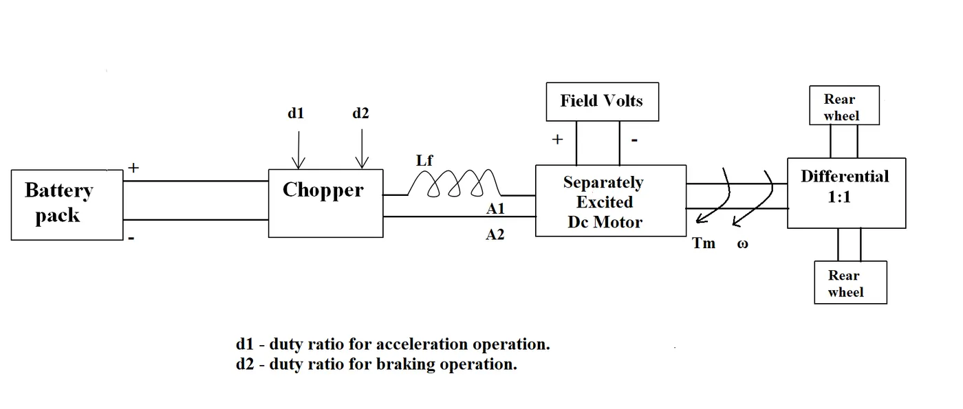
The other parameters of the electric vehicle is given below,
Motor and Controller Parameters:
Rated Armature voltage= 72 V
Rated armature current= 400 A
Ra= 0.5Ω, KΦ= 0.7 Volt second
Chopper Switching frequency= 400 Hz
The vehicle speed-torque characteristics are given by the below equation

What is EV steady state speed if duty cycle is 70%?
3. Refer to the blog on below topic:
Induction Versus DC brushless motors by Wally Rippel, Tesla
Explain in brief about author’s perspective.
EXPLANATION::
STUDY -1>
Power electronic converters:
In electric vehicles and hybrid electric vehicles power electronic technology deals with the processing and controlling the flow of electrical enery in order to supply voltages and currents in a form that is optimally suitable for user end requirements. Power electronic converters uses power electronic componenets such as SCR's , BJTs, TRIACs etc to control and convert the electric power as per user requirements. It is designed is a way that it should produce conditioning power with respect to indivisual applications. The poer electronic circuit consisits of two parts power part and a control part. Power part tranfers the energy from the source to load and it consits of power electronic switches ex TRIAC, transformers, electric choke. The control block regulates the element in the power part of the converter. This blobk consists of low power analog or digital circuit assembly.
Depending on the function performed, Power electronic converters are categorized into following types:
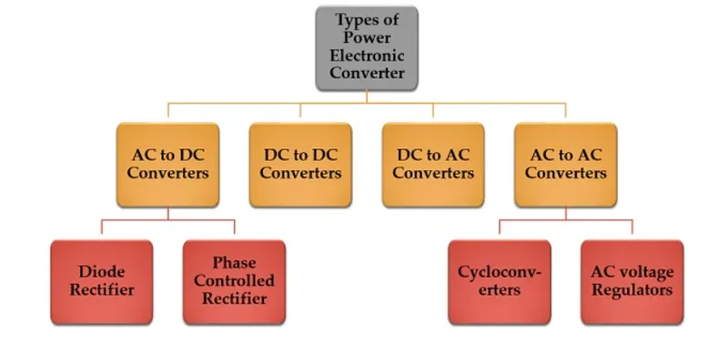
- AC to DC= Rectifier, converts AC to unipolar DC current , The essential components in this rectifier include transformer, switvhing unit, filter and a control block. Here, the transformers adjusts the primary AC source supply to the input of the rectifier stage. It is a step down transformer that reduces the supply voltage to a circuit operating range. The rectifier converts the low voltage AC supply into DC supply. They are of two types uncontrolled diode rectifiers and controlled rectifiers.
- DC to AC= Inverter, converts DC to AC of desired frequency and voltage. The conversion from DC to AC along with variable supply is produced by varying the triggering angle to the thyristors. Most of the thyristors used in inverters are employed with force commutation technique.
- DC to Dc = Chopper, converts constant DC to variable DC or variable DC to constant DC. The chopper circuit is connected between DC input source and DC load. The chopper consists of power electronic switching devices such as thyristors and are connected in such a way that they produce required DC voltages to the load. This method of switvhing is called pulse width modulation(PWM) control. DC choppers are classified into three basic types. Buck-boost converter , Fly back converter, Forward converter.
- AC to AC = Cycloconverter, converts AC of desired frequency and voltage from a line AC supply. These types of power converters are used to convert the alternating current waveforms with different magnitude and different frequency.
STUDY->2
According to the question , given data :
Battery voltage= 72V
D1 and D2 are acceleration and braking dutycycle respectively
Ia= 400V
Ra= 0.5V
K`phi`=0.7 volt secs
Switching frequency= 400Hz
Vehicle speed-torque characteristics equation
T=24.7+0.0051w^2 ......(equ 1)
Answer--> Voltage to motor terminal , at 70% dutycycle (0.7*72)=50.4V
Speed of the motor can be written as:
w=V/k`phi`-(Ra/(k`phi`^2)*Tm)
where w= motor speed
k= motor constant
V= armature voltage
Ra= armature resistance
Torque speed Equation of DC motor is :
T=(V.k`phi`)/Ra - (k*`phi`)^2/Ra *w
Putting values in above equation :
T= (50.4*0.7/0.5)+((-Wm*(0.7)^2)/0.5)
T= 70.56 - 0.98*Wm ...........(equ 2)
Now, we have to match the motor-speed characteristics to the vehicle.
Equ 1 = Equ 2
70.56- 0.98w = 24.7 + (0.0051)w^2
0.0051*w^2+0.98*w-45.86 =0
Here , it is in the form Ax^2+Bx+c, where A=0.0051, B=0.98, C=45.86 and the values can be obtained by --> `(-b+-sqrt(b^2-4ac))/(2*a)`
Putting the respective values we get w=38.91rads/secs
Steady speed of Electric vehicle at 70% duty cycle is 38.91 rad/s
STUDY -->3
Induction Versus DC brushless motor by Wally Ripple, Tesla
Nowadays in the manufacturing of EV's, Lead acid batteries are replaceced by lithium ion batteries, Brushed dc by BLDC , contacters by modulating inverters. He explains about the making construction and working of Im and bldc so we can the fuctioning of two motors. Alike the stator of motors which were similar in construction , the stator of BLDC needed phace inverter and rotor positioning sensor to work. Rotor of BLdc contatins magnets whereas Rotor of IM is made of circular stacked steel laminations with condustor inside them which are shorted at the end. He then says about the limitations in IM. IM doesnt have much torque and have constatt type of speed. but with the help of inverter we can convert DC to AC and the frequency of signal can be varried using the inverter and by adding feedback signal we can also achieve the exact frequency motor wants to run on.
He also explains about High speed low speed characteristics, In brushless Dc we cannot do that because the magnetic field is produced by a permanent magnet, but in induction motor it is possible because it runs on the principle of induction. But still peak performance of brushless dc is higher than induction motor.
CONCLUSION:
Although Dc brushless is better than induction motor in the market and application but induction motors will have its unique application in electric vehicle as well , so both motor applications will grow together .