Week-6 Challenge: EV Drivetrain
1. Which types of power converter circuits are employed in electric and hybrid electric vehicle?
There are 4 main categories of Power converter which are used iin HEV and EV's which are given below :-
1. DC to AC Converters - These converters are connected between DC source of fixed input, and variable AC load. Most commonly, these DC to AC converters are called as inverters. An inverter is a static device that converts fixed DC supply voltage to variable AC voltageThis type of converter takes a DC supply and converts it to an AC one. Power which is supplied from a battery or capacitor can have its form changed to the AC type for use in homes or systems which have an AC load. For instance, the power generated by solar panels are stored in batteries in the DC form and this can power a house which uses an AC power supply so that we can utilise this power from the mains. This type of converter is referred to as an 'inverter' and is widely used in homes and in EV/HEVs.
2. AC to DC Converter - An AC to DC converter circuit can convert AC voltage into a DC voltage.This type of converter takes an input AC waveform with a particular voltage and frequency and outputs a different AC waveform with another voltage and frequency. The output voltage and the freqency can be changed or maintained depending on the application. This converter has many applications in our daily life e.g. lamp dimming, motor speed control. The DC output voltage can be controlled by varying the firing angle of the thyristors. The AC input voltage could be a single phase or three phase.
3. DC to DC Converters - These converters can converter a fixed DC input voltage into variable DC voltage. The DC output voltage is controlled by varying of the duty cycle.This type of converter is similar to a transformer that can change the voltage from its current level to another level. It can take an input supply of voltage and increase it or do the exact opposite and decrease it similar to a step up or step down transfomer. This kind of a converter is called a 'chopper'. The purpose of using this type of converter is to provide the necessary level of power to a particular component and for the safety of the appliance and the user.
4. AC to AC Converter - This converters can convert from a fixed ac input voltage into variable AC output voltage.These type converters are known as AC voltage regulator. This type of converter takes an input AC waveform with a particular voltage and frequency and outputs a different AC waveform with another voltage and frequency. The output voltage and freqency can be changed or maintained depending on the application. This converter has many applications like e.g.motor speed control.
2. An Electric Vehicle's powertrain with 72V battery pack in shown in the diagram below. The duty ratio for acceleration operation is 'd1' and for the braking operation the duty ratio is 'd2'.
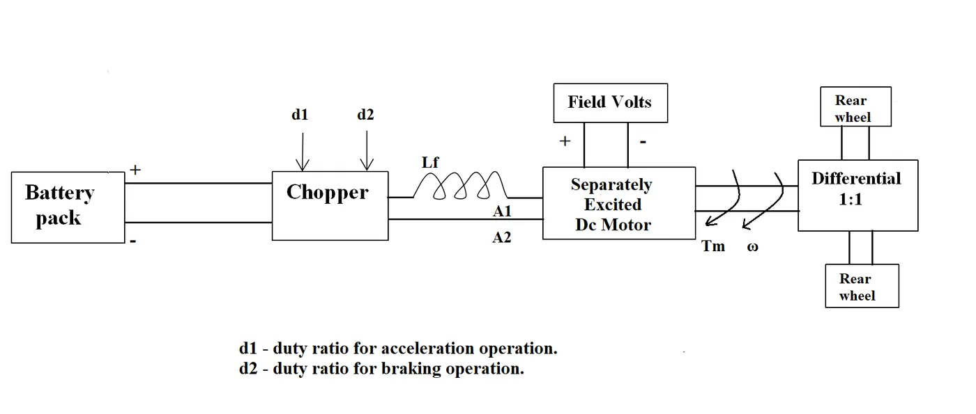
The other parameters of the electric vehicle is given below,
Motor and Controller Parameters:Rated Armature voltage= 72 V, Rated armature current= 400 A, Ra= 0.5Ω, KΦ= 0.7 Volt second, Chopper Switching frequency= 400 Hz
The vehicle speed-torque characteristics are given by the below equation

What is EV steady state speed if duty cycle is 70%?
TORQUE-SPEED RELATION FOR DC MOTOR IS :-
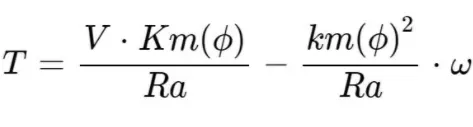
where, Ra = armature resistance
`omega`= angular speed of motor
V= Voltage supply
Km`phi`= Motor constant
T = Torque
Volatge(Motor) = Voltage of armature `*`duty cycle = 72`*`0.7 = 50.4volts
T=`(50.4)*0.7/0.5-omega*(0.7^2/0.5)`
T= `70.56-0.98*omega` .......................... Equation(1)
`Tr = 24.67 + 0.0051*omega^2`.....................Equation(2)
By Equating both the equations we get,
`70.56-0.98omega= 24.67 + 0.0051*omega^2`
`0.0051omega^2+0.98omega-45.89=0`.........................Equation(3)
Solving the eqn3 in Quadratic formula- `(-bpmsqrt((b^2-4ac)/(2*a)))`
`omega=38.92rad//sec`
3. Refer to the blog on below topic: Induction Versus DC brushless motors by Wally Rippel, Tesla . Explain in brief about author’s perspective.
DC Brushless drives use permanent magnets, and cannot change the strength of their magnetic fields. It would be desirable if they could, because when the maximum torque is needed by the rotor, the magnetic field strength should also be at a maximum level. This allows for the inverter and motor currents to be at a minimum, thereby reducing the power loss by heat dissipation. Similarly, when the torque required is minimum, the magnetic field strength should also be minimum to reduce hysteresis and eddy current losses.
For induction drives, the rotor has no magnets, but instead stacked steel laminations with buried peripheral conductors which form a 'shorted structure'. It is the current in the stator windings that generates a rotating magnetic field that interacts with the rotor. Induction motors can be used directly with power from the mains and does not require an inverter to start the drive and generate the starting torque. It has the ability to start under the mains load applied. However, DC brushless drives cannot do the same. They cannot generate a starting torque when connected to a mains power supply. They require an inverter to do this.
In conclusion, Rippel has elaborated the different aspects to compare the induction and DC brushless motor drives and has detailed the advantages and disadvantages of both types. As mentioned earlier, at the end of the day it depends on the preference of the user. If a user is seeking a high performance with comparatively lesser costs, then the induction drive would be better suited for those requirements. However, if it is high peak point efficiency, high power factor and easier control that a user seeks, then the DC brushless drive would be the smarter choice. Both types have their place in the automobile industry and will retain their relevance in their respective applications.