Week 6 Challenge
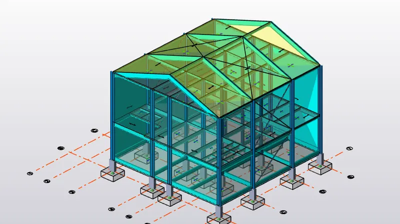
AIM: To summarize the bending moment, shear force and deflection diagrams for the elements of the model.
INTRODUCTION: while designing wheather members are suitable for the construction purpose or not can be decided based on the analyses result which include the bending moments
PROCEDURE:
- in order to obtain bending moment and shear force diagram,analyses has to be continued.
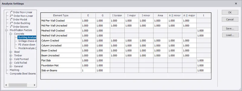
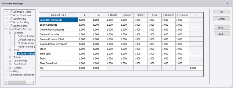
- analyses>setting>1st order analyses.
- check for modification factor for concrete and tsee.
- initially for first analyses,it should be 1.If any other values chage to 1.
- click on first order analyses,analyses will run.
- at bottom right corner,click on result view.
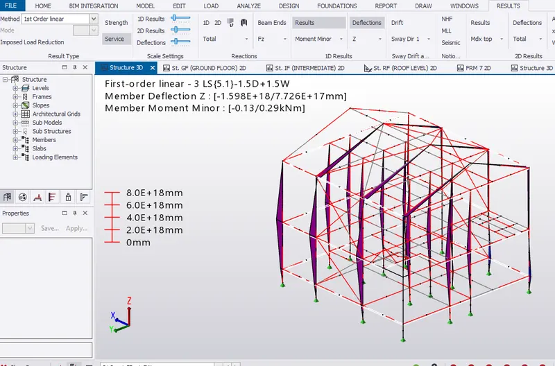
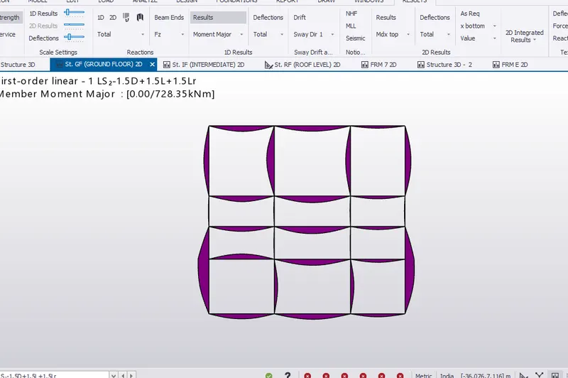
a.Bending moment-
- A bending moment (BM) is a measure of the bending effect that can occur when an external force is applied to a structural element.
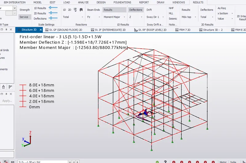
- In tekla in result view we can find clear bending moment of each member under different loading cases and combination.
- from the obtained bending moment for major and minor,the major bending is near staircase location.
b.shear force-
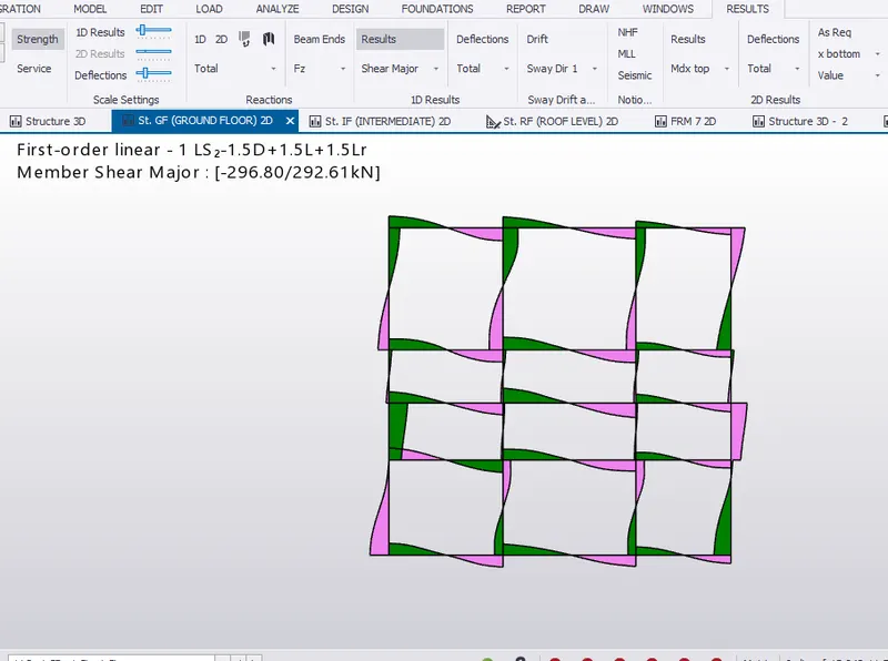
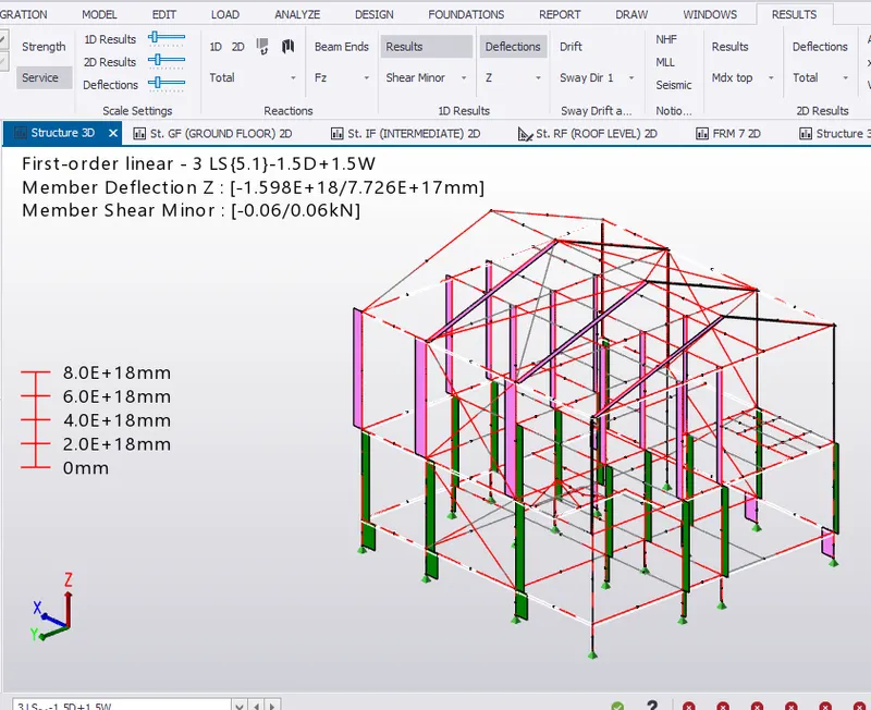
- Shear force is a force acting in a direction that's parallel to a surface or cross section of a body.
- the shear force of ground floor is as per the expected,and in intermediate floor,it is more at staircase beam side.
- shear force of the column vary floor to floor.
c.deflection diagram-
- Deflection means the movement of a beam or node from its original position. It happens due to the forces and loads being applied to the body.
- Deflection also referred to as displacement, which can occur from externally applied loads or from the weight of the body structure itself.
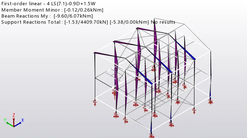
RESULT: the bending moment, shear force and deflection diagrams for the elements of the model is studied.
AIM: Based on the analysis design the members and outline the thought process in selecting the member sizes along with the foundation design
INTRODUCTION: Structural analysis is important as it provides a basis for structural design and also it evaluates whether a specific structural design will be able to withstand external and internal stresses and forces. The structural analysis helps to determine the cause of a structural failure.
PROCEDURE:
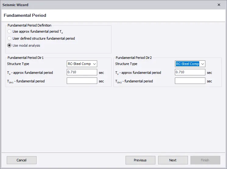
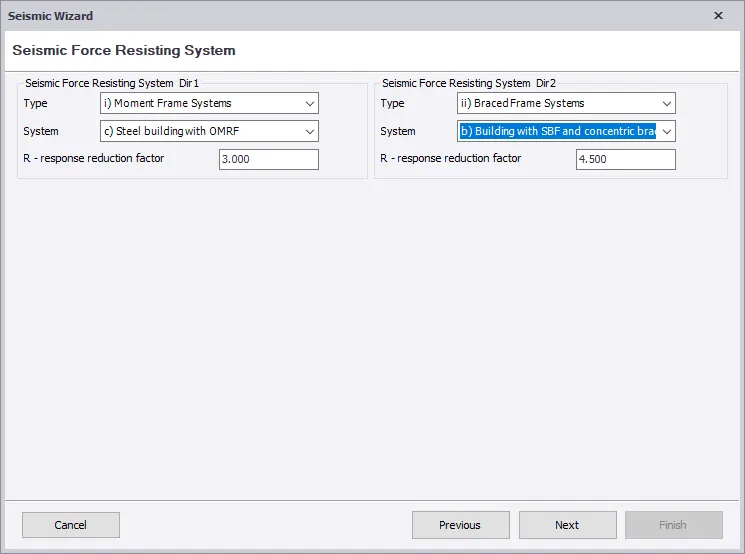
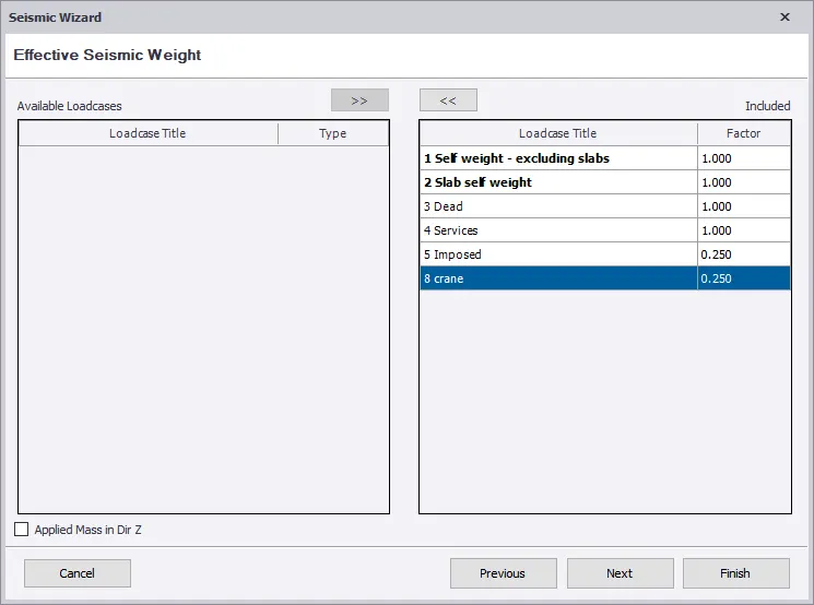
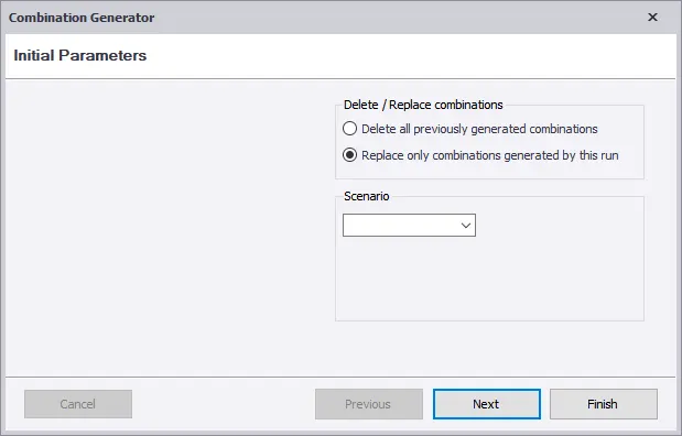
- add seismic load to the structure using structural wizard
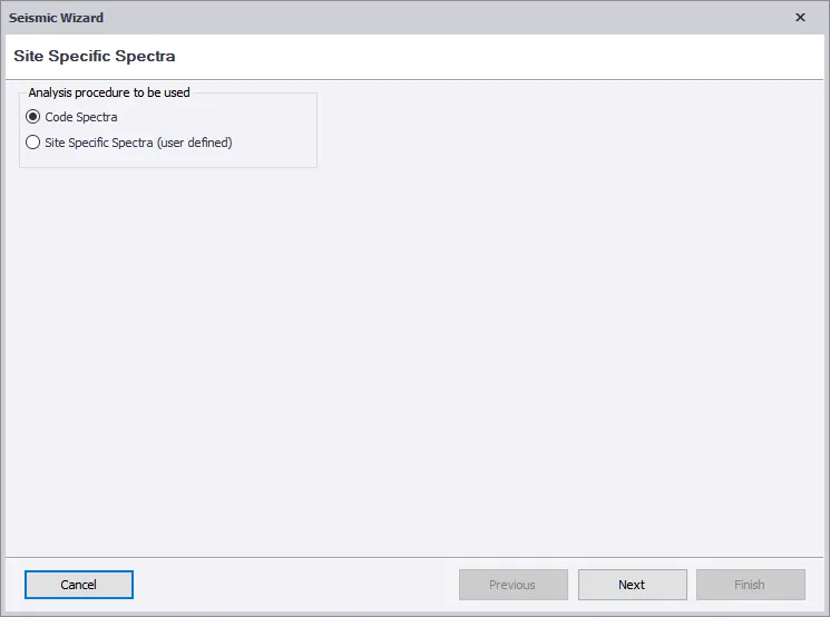
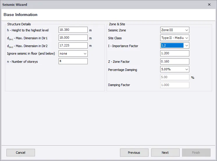
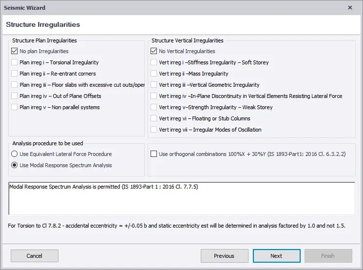
- analyses>setting>1st order analyses.
- check for modification factor for concrete and tsee.
- initially for first analyses,it should be 1.If any other values chage to 1.
- click on first order analyses,analyses will run.
- at bottom right corner,click on result view.
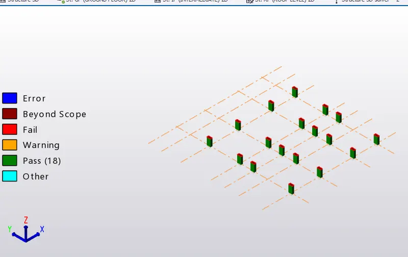
- select individual frame,select the beam first and right click.now select check selection/member.
- check if it pass all criteria,if not see the property and change the member.
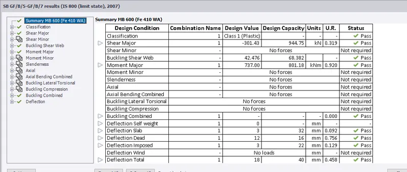
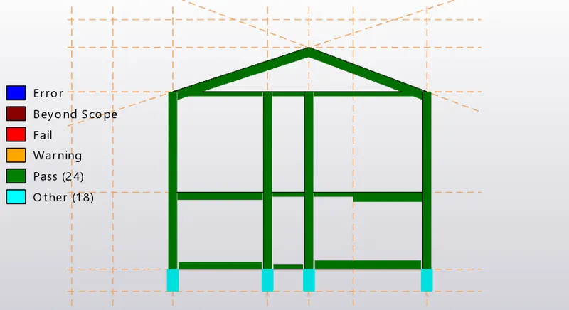
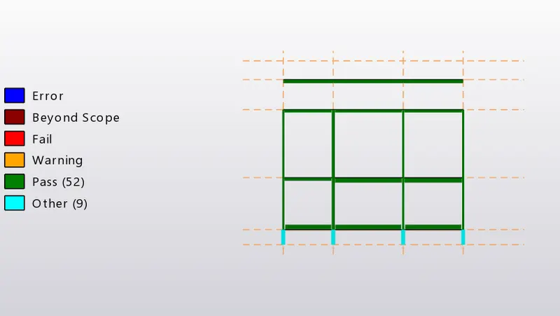
- as per the loads applied,beam section varies from 300-600Mb.
- rafter beam size is Universal beam 610x305x149.
- the steel column size is 600MB.
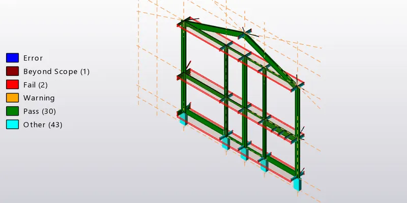
- the concrete passed all criteria without any change.
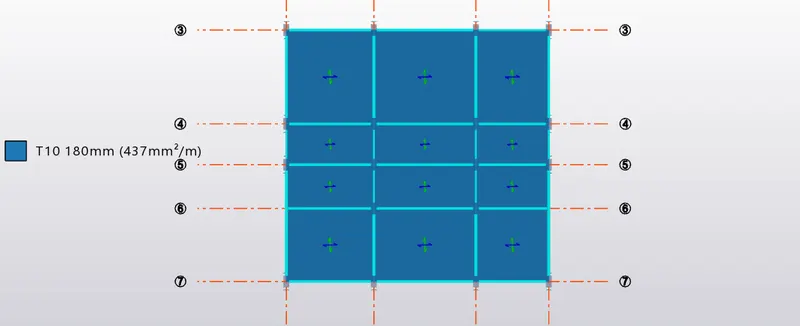
- for slabs,design>design slab.
- review view>slab reinforcement,changed to 10 mm dia at 150mm c/c.
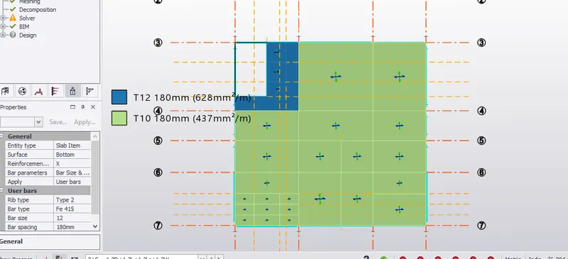
- for foundation modeling,foundation>paded foundation>cick on pedestarin.
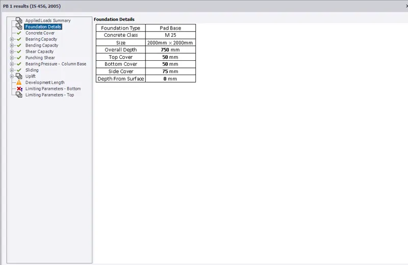
- the foundation of size 2x2x0.75m size is modeled.
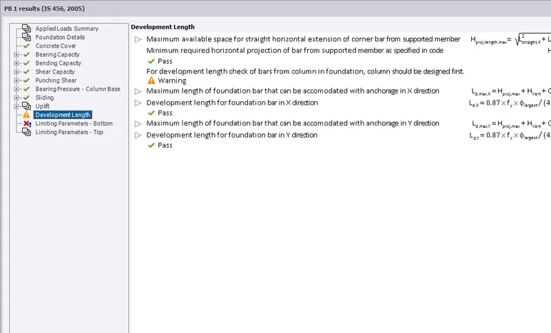
- similar to beam and column check the detail of foundation criteria.
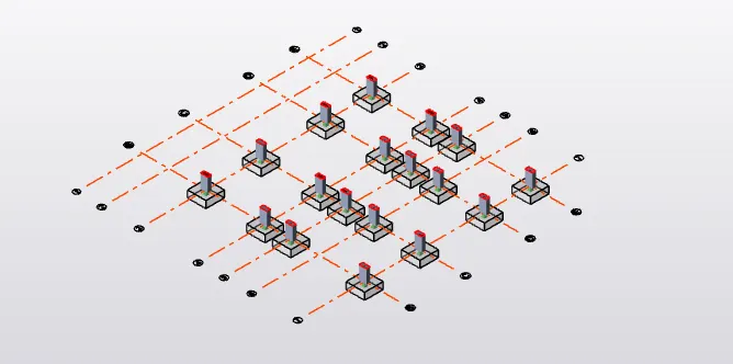
RESULT: based on analysis,member are checked and resized.Also foundation is modeled.