Creating a Floor plan, Footing detail and Isometric view using AutoCad
AIM:To create cross section of load bearing wall over spread footing using autocaed.
Command uses:
Line-To create whole cross section of wall.
Rectangle-to create rectangle at required section.
Offset-To create some line at known particular distance.
Trim-edit/delete unwanted or extra line crossing over another lines.
Dimension-to display the dimension of each section/line.
Text- to type given heading/text.
PROCEDURE:
step 1-Set the drwaing sheet-
- Enter UNITS in command section-let typebe decimal with 0.00 precision.
- Insertion scale be in milimeters with and lighting be internatinal-select OK.
- Page limit can be setup in two ways-LIMAX or limits.
- In LIMAX-command ,enter the maximum coordinate of the page as 50,50.
- In limit-command,enter left corner coordinate as 0,0 and right most coordinate as 50,50.
- Enter ZOOM in command bar and select ALL-enter.
- start with the drawing.
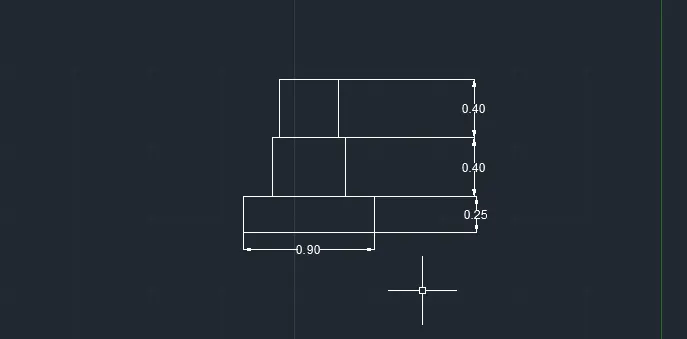
step 2- Create footing layer
- Type "rec" in command bar.
- specify first corner point on the drawing sheet and select dimensions.
- enter length as 0.9 and width as 0.25,select second corner to place.
- draw a center vertical line from rectangle upto 1m height and horizontal line on rectangular top width of 0.9 distace.
- type "offset" in command bar and enter offset distance as 0.25.
- Offset the center line on either side.
- press Esc to exit from offset.
- right click on mouse and select repeat offset command .
- enter offset distance as 0.4 and select top width line to offset.
- Repeat the same procedure offset of 0.2 on either side of center line and 0.8 for horizontal offset from rectangular top width.
- trim the unwanted line referring figure.
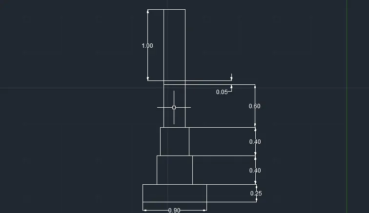
step 3:draw of load bearing wall:
- repeat same offset procedure as in step two.
- offset distance of 0.15 on either side of central line.
- offset distance of 0.6,0.65 and 1.65 from column horizontal line.
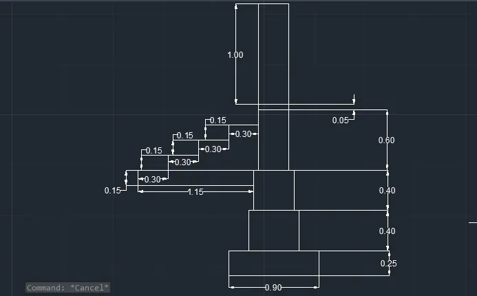
step 4:draft of slab and staircase steps.
- extended a hozintal line from column end.
- offset distance of 0.15,0.3 and 0.45 from extended horizontal line.
- similarly offset of 0.3,0.6,0.9 and 1.2 from load bearing wall.
- offset of 0.15 below from extended hozintal column line.
- trim off unwanted lines referring figure.
- select text option from ribbon,specify height and width of text.
- click on drawing page to enter the text and type.
Result:
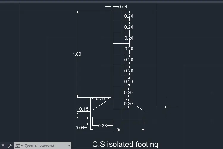
AIM:Creation of C.S of isolated footing
PROCEDURE:
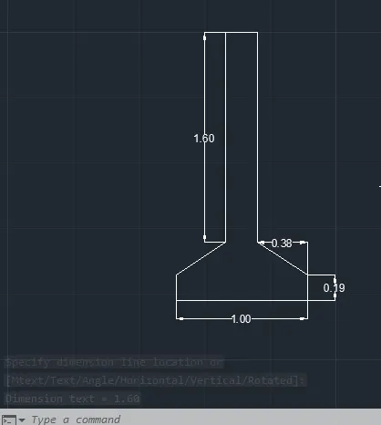
step 1- drafting outer geometry.
- select ine from draw pannel in ribbonn.
- specify one corner and enter @1,0.
- specify next coordinate as @0,0.19.
- specify next coordinate as @0.38,0.25.
- specify next coordiate as @0,1.6.
- specify next coordinate as @-0.24,0.
- specify next coordinate as @0,-1.6.
- specify next coordinate as @-0.38,-0.25.
- click on close to end the drafting.
step 2:drafting of interior footing
- select offset from modify panelin ribbon.
- enter offset distance as 0.04 and offset column both side inside direction,extended the line till base of footing.
- press esc to exit from the option.
- press enter to repeat the command offset.
- offset distance of 0.2 from top width of column,repeat 9 times from consective offseted line.
- repeat offset with distance of 0.04 from base line of footing and 0.38 from side of interior footing.
- trim the unwanted lines with refrence to given figure.
Result:
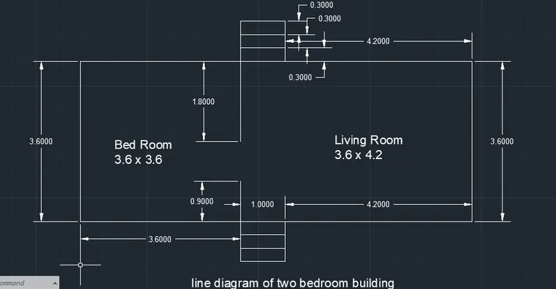
AIM:draft line diagram of two bedroom building
Procedure:
- select ine from draw panel.
- specify one corner annd enter distance as 8.8 @=ve x-axis.
- specify next coordinate as 3.6 @+ve y-axis.
- specify next coordinate as 8.8 @-ve x-axis.
- specify next coordinate as 3.6 @-ve y-axis.
- now type offset in command bar and set offset distance as 3.6.
- select offset object as left side width of house and directed towards right side.
- press Esc to exit from the command.
- press enter to repeat the offset,set distance as 4.2.
- select the object as right side wall and direct towards left side.
- for drafting stairs of both side,draw aline between offset line.
- select offset from modify panel from ribbon,distance as 0.3 and repeat 3 times on both sides.
- trim two unwanted lines on right side of stairs.
- select extended and specify distance to extend line on both left side of stairs at distance 1.8 of upper stirs and 0.9 of lower stairs.
- select text option from ribbon,specify height as 0.1 and width of text.
- click on drawing page to enter the text and type.
Result:
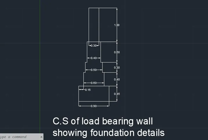
AIM:C.S of load bearing wall showing foundation details.
Procedure:
- select line from draw panel in ribbon.
- specify one corner to start and enter first coordinate as 0.45 in +ve x-axis.
- specify next coordinate as 0.45 @+ve y-xis.
- specify next coordinate as 0.15 @-ve x-xis.
- specify next coordinate as 0.40 @+ve y-xis.
- specify next coordinate as 0.05 @-ve x-xis.
- specify next coordinate as 0.30 @+ve y-xis.
- specify next coordinate as 0.05 @-ve x-xis.
- specify next coordinate as 0.60 @+ve y-xis.
- specify next coordinate as 0.05 @-ve x-xis.
- specify next coordinate as 1.00 @+ve y-xis.
- specify next coordinate as 0.15 @-ve x-xis.
- similarly repeated smae steps on the other side.
- select mirror command from modify panel.
- select the whole object and press enter.
- specify the corner end point and direct cursor upwards.
- select line and draw horizontal line for pcc bed and ground level.
Result:
AIM:Isometric view of gabble wall
Procedure:
keep the iso drawinf on,ortho on and snap mode off.
step 1- from iso-left drawing portion
- select line command from draw panel in ribbon.
- move the cursor right side and enter distance as 0.3.
- specify next coordinate as 3 in +ve y axis.
- specify next coordinate as 0.3 in -ve x-axis.
- click on close to complete the line.
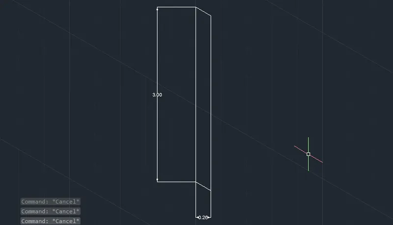
step 2-from iso left command drawing
- enter again to repeat command line,select the corner of previous drawing to start.
- specify coordinate as 1 in +ve x-axis.
- specify next coordinate as 2.42 in +ve y-axis.
- specify next coordinate as 1 in +ve x-axis.
- specify next coordinate as 2.42 in -ve y-axis.
- specify next coordinate as 1 in +ve x-axis.
- specify next coordinate as 3 in +ve y-axis.
- enter esc to exit from line command.
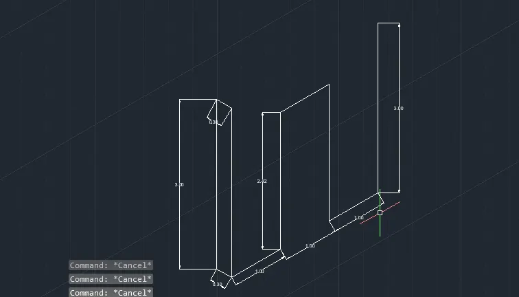
step 3-iso left portion
- select line command,enter 0.3 distance towards -ve x-axis at door.
- specify next coordinate as 2.42 @+ve y-axis,press esc.
- press enter to repeat line command,to make slope portion of wall.
- draw a line at center of door at a distance of 3.25.
- join both side of wall corner to that line.
- sepcify 0.3 as next coordinate and join another corner of wall.
Result:
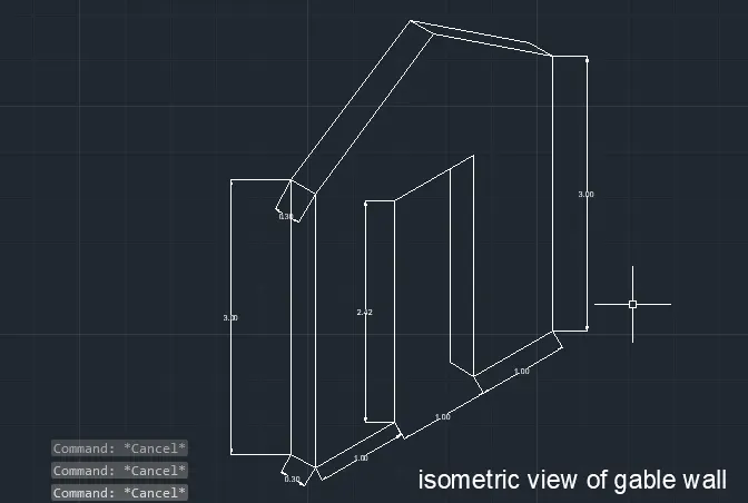
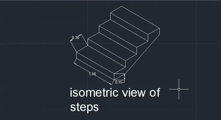
AIM:isometric view of steps
Procedure:
off the object snap,let ortho be on.
- set isoplane left on.
- select the line command from draw panel.
- select a corner,enter frist coordinate as 1 @+ve x-axis.
- specify next coordinate as 0.15 @+ve y-axis.
- specify next coordinate as 1 @-ve x-axis.
- specify next coordinate as 0.15 @-ve y-axis.
- change to isoplane top and continue line command.
- specify the coordinate as 0.30 front.
- specify next coordinate as 1 and cursor towards right.
- specify next coordinate as 0.3 keeping cursor back.
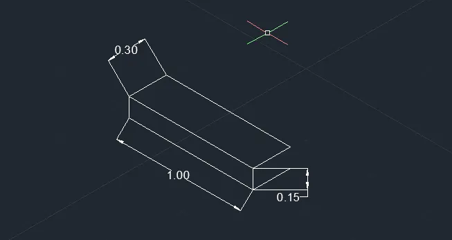
- change to isoplane right,enter copy in command bar.
- select one whole step,point corsor at step corner point and paste.
- repeat the same for two more steps.
- change to isoplane left,select line and draw a line atend of steps with 0.15 unit @-ve y-axis.
- join the first and last steps line.
Result: