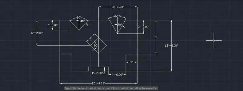
Drafting of various geometries using Chamfer, Fillet tool in AutoCad
AIM:to create various geometric shapes using chamfer and fillet tool in Autocad.
INTRODUCTION:
Chamfer-It is a modification tool used for making slanted edges.It can created by specifying either the chamfer distance or angle.
Fillet-It is also a modification used to create rounded edges between the adjacent lines.It can also connect two adjacent lines and two tangnet acrs.
COMMAND USED-
- Line
- circle
- chamfer
- fillet
- offset
- trim
- move
- rotate
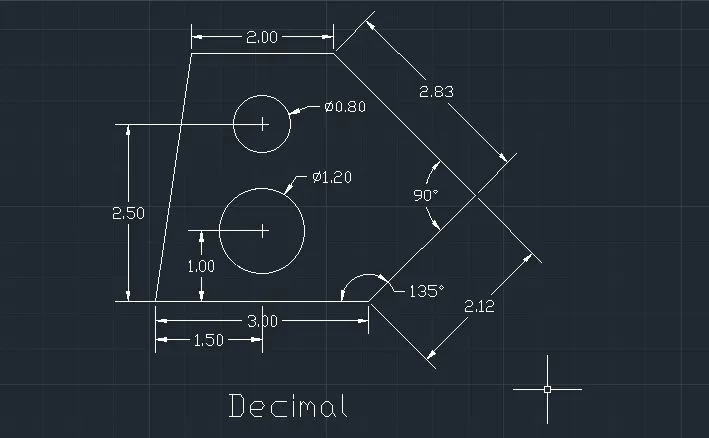
1.To create given geometric shape using decimal units.
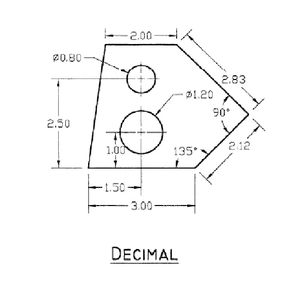
PROCEDURE:
- type units in command line and set as decimals with 0.00 precision.
- press ctrl+n for new setting,select advance setting.
- in angle direction choose north as refrence and clockwise as positive direction.
- select line command from draw panel and specify one corner to start.
- specify first coordinate as @3,0.
- specify next coordinate as @2.12<45.
- specify next coordinate as @2.83<-45.
- specify next coordinate as @-2,0.
- click on close to complete the shape.
- select offset and specify 1.5 distance.
- choose left corner line as offset towards right.
- similarly offset bottom 3unit line with 2.5 and 1 distance.
- at intersection of 1.5,2.5 offset line,select circus and diamter.
- click on intersection point and specify diamter as 0.8.
- similarly circle with diamter 1.2 keeping intersection point of 1.5,1 as a center.
- select linear dimension for linear line measuring,angular dimension to measure angle and alinged for slanted line dimension.
RESULT:
2.To create given geometric shape with architecural units.
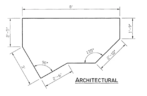
PROCEDURE:
- ctrl+n for new advance setting select architecural units with precision of 0'-0".
- angle reference as east and anticlockwise as positive direction.
- select line command and specify a corner.
- specify first coordinate as @2'6"<210.
- specify next coordinate as @3'<120.
- specify next coordinate as @2'5"<90.
- specify next coordinate as @8'<0.
- specify next coordinate as @1'9"<270.
- specify next coordinate as @2'10"<225.
- click on close command to complete the shape.
RESULT:
3.To create given geometric shape with engineering units.
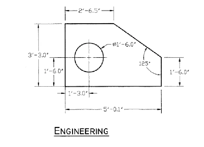
PROCEDURE:
- type UN for units in command bar and select engineering with precision 0'0.00".
- select line command and specify a corner point.
- specify first coordinate as @0,-3'3.0".
- specify next coordinate as @5'0.1",0.
- specify next coordinate as @0,1'6.0".
- press esc to exit from line command.
- press enter to repeat the command,specify top point of left vertical line.
- specify the coordinate as @2'6.5",0 and next join the line with right vertical top point.
- select offset from modify panel and set offset distance as 1'3.0".
- offset left vertical line towards right.
- similarly repeat the command,specify distance as 1'6" and offset bottom line.
- select circle with diameter command and sepcify center as intersection point of offset line.
- enter diamter as 1'6.0" and trim offset lines.
RESULT:
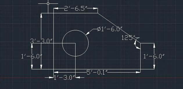
4.to create given geometric shape using polyline
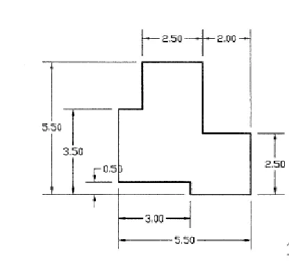
PROCEDURE:
- type units and select decinmal with 0.0 precision.
- select polyline from draw panel and specify a corner.
- specify the distance 3 to right,0.5 towards down,2.5 to right,2.5 to top,2 to left,3 to top, 2.5 to left,2 to down,1 to left and click on close.
Result:
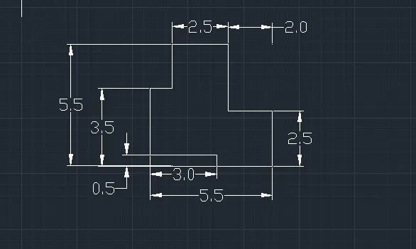
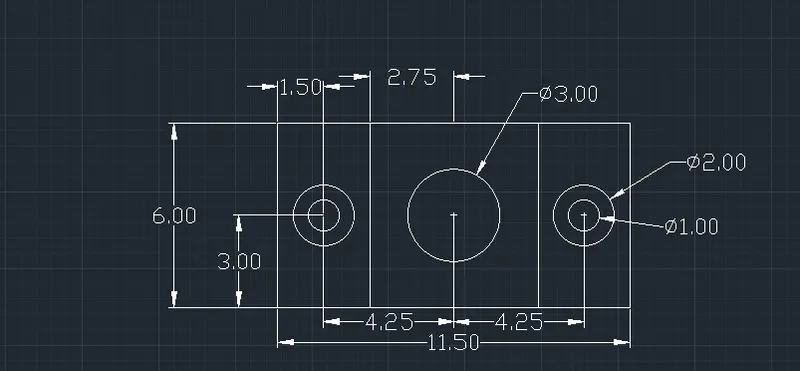
5.to create given geometric shape using line,circle,copy and scale command.
PROCEDURE:
- select lie command and specify a corner.
- enter the coordinate as @0,6.
- specify next coordinate as @11.5,0.
- enter the coordinate as @0,-6.
- click close on command bar.
- select offset and enter distance as 3.
- select bottom length and offset towards top.
- similarly offset left width of offset distance for 1.5,3,4.25,5.5 and 10 towards right.
- select circle with diamter and draw first circle with center as intersection of first offset line and diamter 2.
- select scale command,click and circle and enter scale down value as 0.5 with same center.
- enter copy command and select 2 concentric circle,paste on right side.
- similarly circle with diamter command ,center as midnight of lines with diameter as 3.
RESULT:
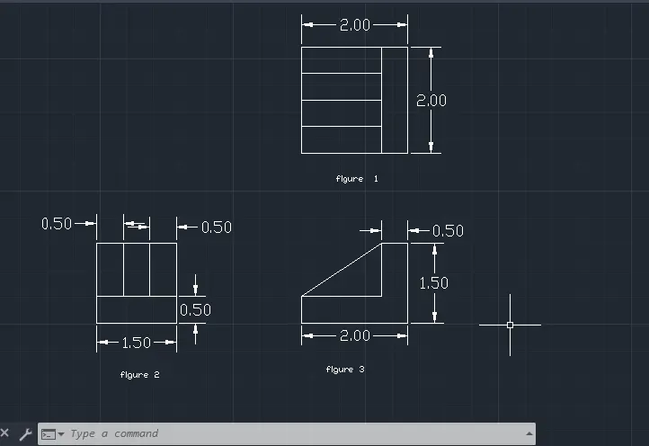
6.to create given geometric shape using line,trim,offset and chamfer command.
PROCEDURE:
- select the line command and specify a corner.
- enter first coordinate as 2 @+ve x-axis.
- specify next coordinate as 2 @+ve y-axis.
- specify next coordinate as 2 @-ve x-axis.
- click on close on command bar.
- select offset from modify pannel,specify distance as 0.5.
- selct right side of square and offset towards left side,similarly select bottom side and offset towards top two times.
- to create figure 2,create a square of each side 1.5 units.
- offset both sides by 0.5 units and also bottom side by 0.5.
- select figure 2 and click on rotate symbol.
- specify the base point and enter 90 degree.
- below figure 1, create a rectangale of length 2 and width 1.5 using line command.
- offset with same 0.5 distance from bottom side and right side line.
- type chamfer in command line and select dimension in option.
- enter first dimension as 1.5 and second dimension as 1.
- select 1st and 2nd line to chamfer and press enter.
RESULT:
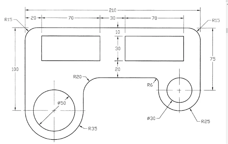
7.to create given geometric shape using line,offset,trim and fillet command.
PROCEDURE:
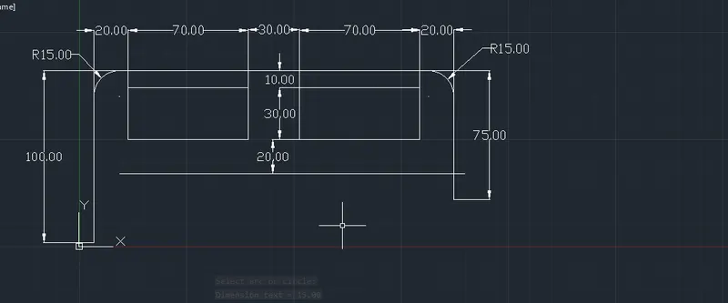
step 1-to create geometry shape upper portion.
- select line command from draw panel and specify a corner point.
- specify coordinate as 100 @+ve y-axis.
- specify next coordinate as 210 @+ve x-axis.
- specify next coordinate as 75 @-ve y-axis.
- select offset command and enter distance as 10,30 and 60,select 210 unit line and offset downwards.
- similarly offset at distance 20,90,120 and 190 from left 100 unit line.
- enter fillet in command bar and select radius.
- enter radius as 20 and select 100 as 1st line and 210 unit line as second,press enter.
- similarly in opposite side,repeat the same.
step 2- to creat lower portion.
- select 2 point circle command and click end point of 100 unit line as 1st point.
- specify diamter as 70,press enter.With the same center draw circle with diamter 50.
- similarly in opposite,with diamter 50 and 1st point as 75 unit line end.With same center draw circle with diamter 30.
- select fillet command and specify radius as 35.
- select circle with 70 diamter and bottom line of upper portion,press enter.
- similalry fillet circle of 50 diamter and line with radius 6.
RESULT:
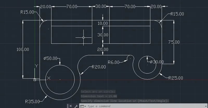
8.to create given geometric shape using line,circle,trim and fillet command.
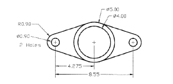
PROCEDURE:
step 1- to draw all circle portion.
- select circle with diamter command and specify one centre.
- specify the diameter as 0.4 and with same center draw one more circle with diamter 0.5.
- enter L command and draw a line with distance 4.275 on either side from centre of circle.
- at end point of both line,draw a circle with diamter 0.9 using circle command on either side.
- erase the 4.275 unit line.
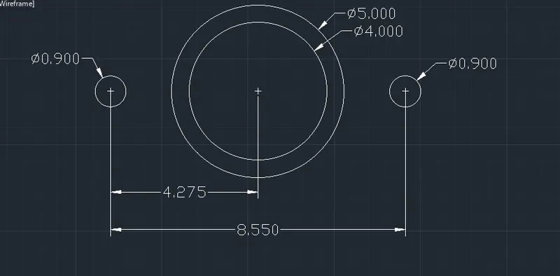
step 2- to draw outer fillet portion.
- select line command and draw tangnet to circle of diamter 5 on both sides and ends of circle.
- select fillet command and specify radius as 0.9.
- select the two tangnet line to be fillet,repeat the same on other side also.
RESULT:
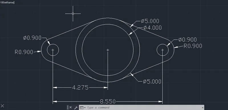
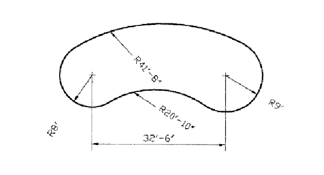
9.to create given geometric shape using line,circle,trim and fillet command.
PROCEDURE:
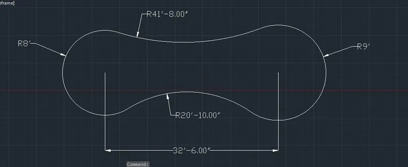
- select a line command and draw line of length 32'-6".
- from end point of line,draw a circle of radius 8' on left side and 9'on right side using circle command.
- select fillet command and enter radius as 20'-10",select lower sides of circle and press enter.
- similarly fillet upper side of circle with radius 41'-8".
- trim off the unwanted portion of circle and line.
RESULT:
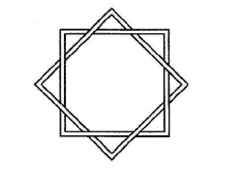
10.to create given geometric shape using rectangle,offset,rotate and move command.
PROCEDURE:
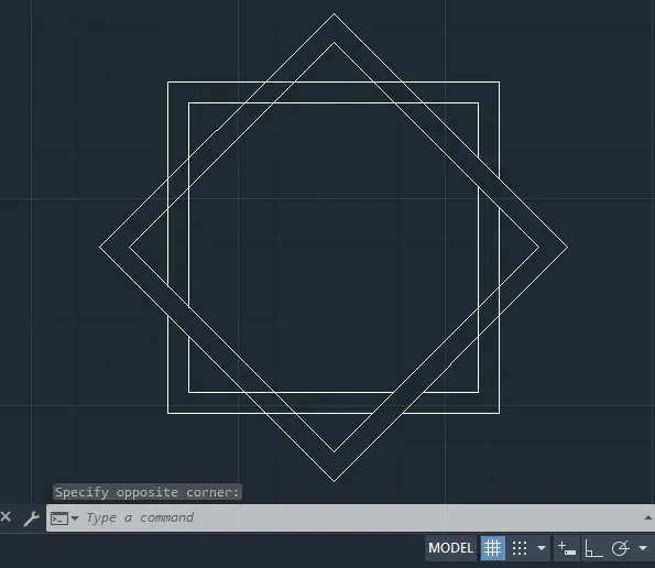
- select rectangular command from draw panel and specify dimension of length and width 4 units.
- offset the rectangle inside with offset distance of 0.25.
- select the object, copy the object and rotate by 45 degree.
- move the rotated object keeping center as base point and place in center of rectangle.
- use breakpoint to break the length at intersection of both rectangle and deleted breakline as required.
RESULT:
11.to create given geometric shape using line,offset and trim command.
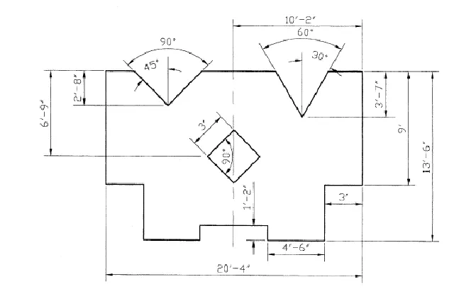
PROCEDURE:
- set units to be in engneering and select line command.
- specify the corner,first coordinate as 6'9"@-ve y-axis.
- specify next coordinate as 3' @+ve x-axis.
- specify next coordinate as 4'-6" @-ve y-axis.
- specify next coordinate as 4'-6" @+ve x-axis.
- specify next coordinate as 1'-2" @+ve y-axis.
- specify next coordinate as 4'-6" @+ve x-axis.
- specify next coordinate as 4'-6" @+ve y-axis.
- specify next coordinate as 3' @+ve x-axis.
- specify next coordinate as 9' @+ve y-axis.
- click on close command.
- select offset command,distance as 3'-7" and 2'8" from top line towards down.
- also offset a distance of 5'1" from both sides towards centre.
- select line command and draw a line from offset intersection point with angle 30 either side in right and join the slanted lines to main line.
- similalrly towards left side, from intersection point at angle of 45 on either sides and join to main line.
- trim off unwanted offline lines.
- for inner rectangle, make a rectangle of sides 3' at center and rotate about 45 from reference line.
- move the rectangle and place at vertical distance of 6'-9" keeping same geometric centre.
RESULT: