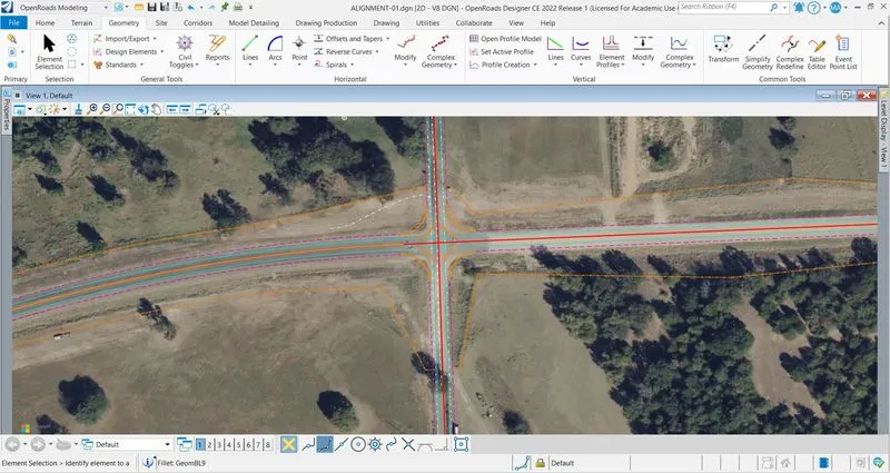
Week 6 Challenge
1. Create a MicroStation rectangle, complex line and apply civil rule features to the same with linear > matchline feature definition.
2. Build geometry of your own parameters with geometry builder tool.
3. *Design an alignment on the 1st intersecting street. Design the proposed profile for the same. Name the alignment as “INT_01” and “PGL_INT_01”. Assign stationing starting from start of the alignment with 50+00.
4. *Design the roadway layout for this intersecting street till the survey/topo limits. Use above alignment as a starting point. Refer to the parameters from week 5 challenge # 01, 02. Create driveway and intersection openings referring to the background imagery.
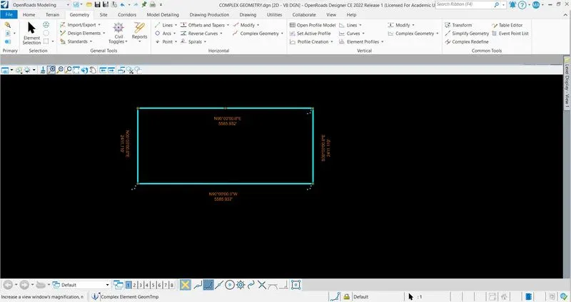
Q-1 : CREATE A MICROSTATION RECTANGLE :
Create a file named as "COMPLEX GEOMETRY" with 2D SEED > Click on drawing tab > Click on rectangular block > Draw a rectangle > Click on geometry tab > Design elements > Create civil rule feature > Tool open > Set the feature defination > Locate the rectangel > MicroStation rectangle is created.
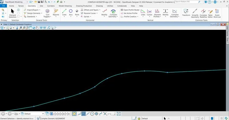
Q-2 : GEOMETRY :
Click on Complex Geometry tab > Geometry Builder > Click on add new geometry logo > Named as ALIGNMENT > Click on Bearing > Click on Begin Point to locate point > After locating point we can
create alignment by line and curve > Place > Close > Save as Alignment > Ok.
Q-3 : DESIGNING THE ALIGNMENT :
Create a file named as "ALIGNMENT-01" with 2D SEED > Set the co-ordinate > Reference the Topo, Existing and Proposed file > Set the level display as per convinent.
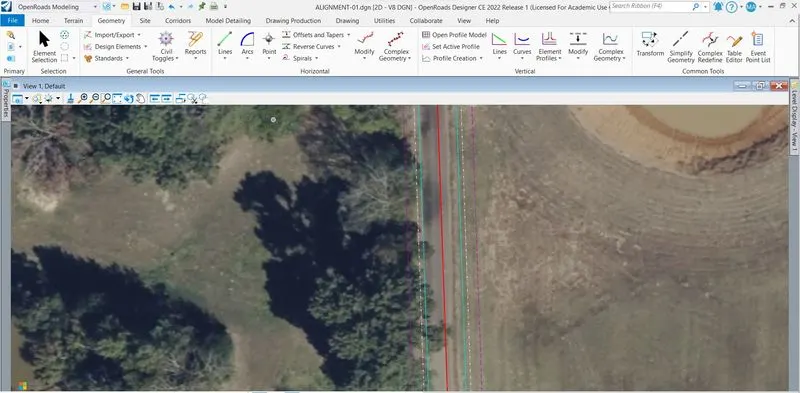
Copy the boundry line and put it on its original position (do for both sides) > Click on Complex Geometry > Define by best fit > Select the copied line > Fill the civil rule > Repeat the above procedure at different station to install good alignment > Click on arc > arc between elements > Simple arc > Select the two lines which generated through the best fit > Set the radius > Alignment is created > Make it complex by Complex by Element.
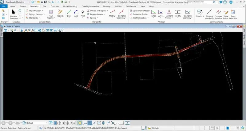
Same procedure is repeated for intersection point to generate new alignment across the main alignment(INT_01); named as "PGL_INT_01".
Q-4 : DESIGN THE ROADWAY LAYOUTS :
Click on Offset and Tapers > Single Offset Entire Elements > Set the appropertiate feature defination and offset length for edge of pavment and shoulder > Join them on the intersection with best fit curve.