Project 2
PROJECT 02 ASSIGNMENT
1. Complete a project based upon all previous lectures.
2. See completed .PDF as a go-by for project criteria.
STEP-1 :
Open a drawing file with given template "COMPANY_XYZ" and save as "ALGNRD-02".
Open the given topographic "TOPORD01" file and copy all given data and paste it to the original co-ordinate in "ALGNRD-02".
Step-02 :
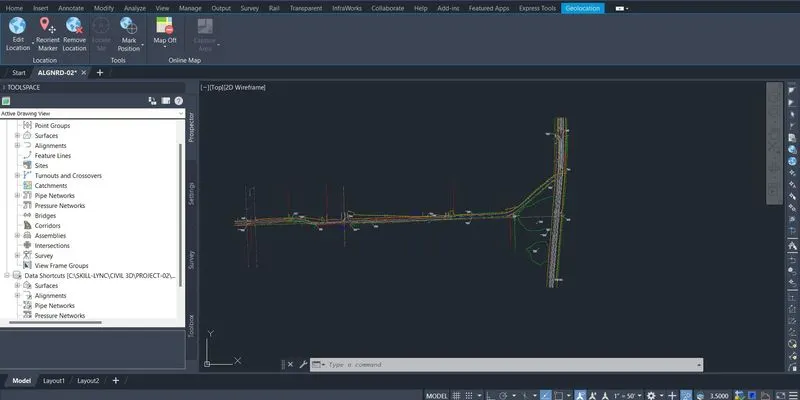
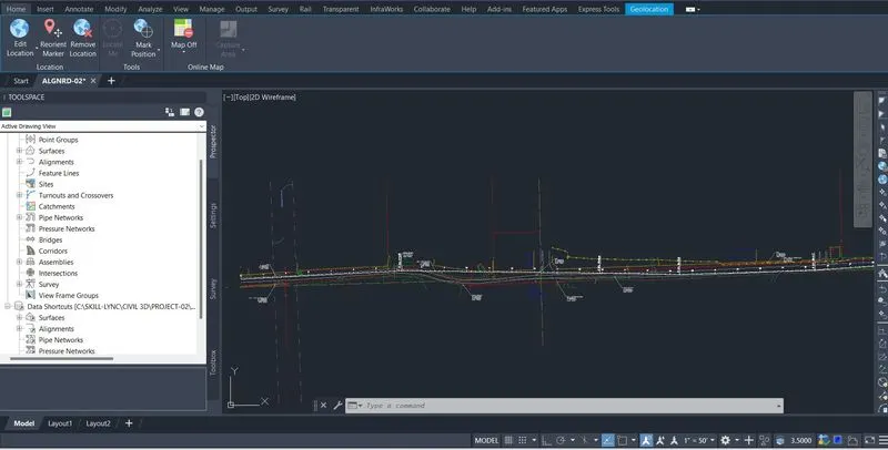
Click on Alignment tab in menu bar > Create alignment by layouts > Fill all the given option and name the alignment "ROAD-02" > Ok > Alignment layout tools open > Select fixed line (two points) and draw staright path > Select free spiral-curve-spiral (between two entities) and draw where the curve is required > Alignment is created.
Step-03 :
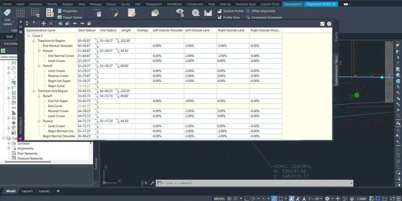
Click on alignment tab in menu bar > Select super-elevation > Calculate / edit super-elevation > Calculate super-elevation now > Undivided crowned > Center baseline > Ok > Super-elevation is calculated.
Step-04 :
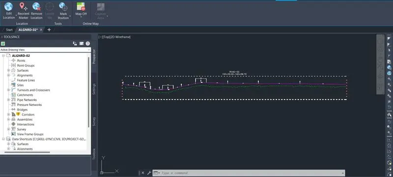
Click on profiles tab in menubar > Create profile from surface > Select alignment "ROAD-02" Select surface "SURVEY SURFACE" > Add > Draw in profile > Select all different options > Ok > Profile cretaed > Select the grid option > Close the major and minor grid > Ok.
Click on profile tab > cretae profile by layouts > select the layouts > Profile layouts tools open > select draw tangent > Draw tangent from first point to last point > Select PVI > Install PVI where alignment needed the PVI > Select curves (Parabola) > Smoothing the alignment > Profile is created.
STEP-05 :
Click on corridors tab in menu bar > Create assembly > select all given option > Ok > Select assembly > open tool palates > Install required items in assembly for ROAD-02(A) > Repeat all above procedure for assembly ROAD-02(B).
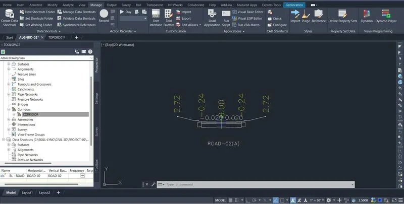
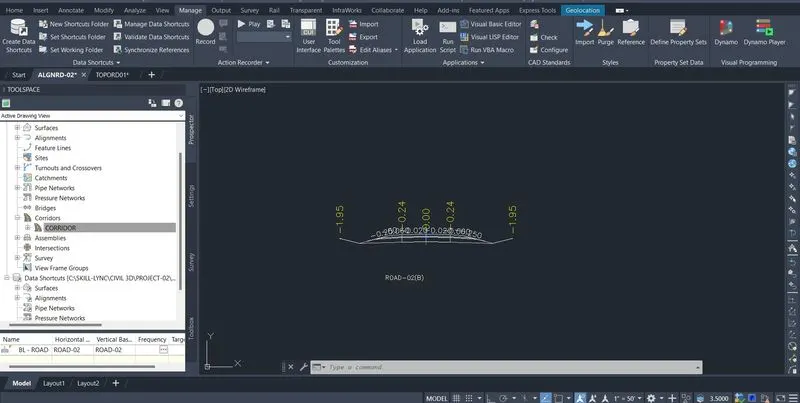
Go to the prospector tab in toolspace > expand corridor > right click on CORRIDOR > Properties > right click on assembliy > Select the start and end station of two different region > Set the frequency > Set the target > apply > Rebuild the corridor > Corridor rebuilt.
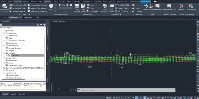
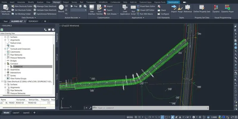
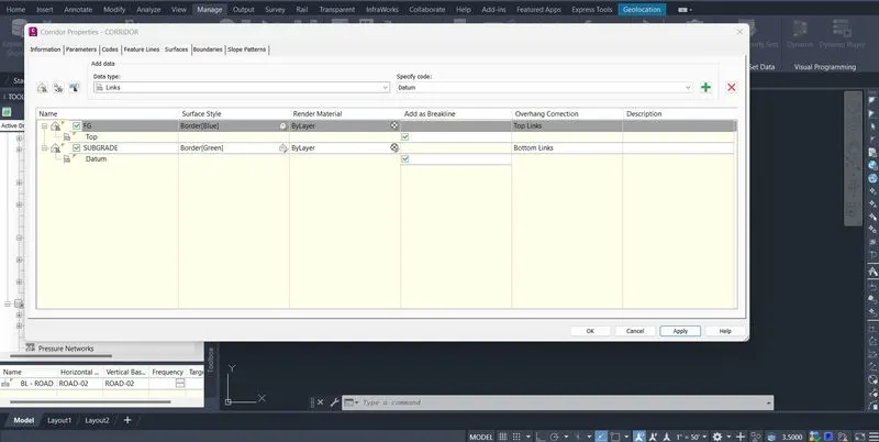
Go to prospector tab in toolspace > expand corridor tab > Right click on "CORRIDOR" > Properties > Surfaces > Click on "Create a corridor surface logo" >Specific code "Top" > Click on '+' sign > Select overhang correction as top links > Named as FG > Select overhang correct as bottom links > Named as subgrade > Check the box > Apply > Ok.
Step-06 :
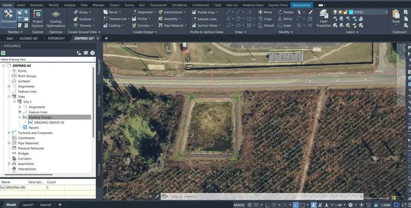
Create a new file names as DRPRRD-02 > On the geolocation (AERIAL) > Figure out the pond area > Create a enclosed line of elevation of 95' > Layer is installed > click on feature line tab > Create feature line from object > Select pond line > Featured line is created > Click on grading > open grading creation tools > select all given option and grading is installed.
Step-07 :
Click on home ribbon bar > Pipe network > Create pipe network > network name "PIPE NETWORK" > Surface name "SURVEY SURFACE" > Alignment name "ROAD-02" > Pipe lebel style "Profile-length description and slope" > Ok > Select 12-inch flared end section 67*74 > Select 12 inch concrete pipe > place the pipe network.
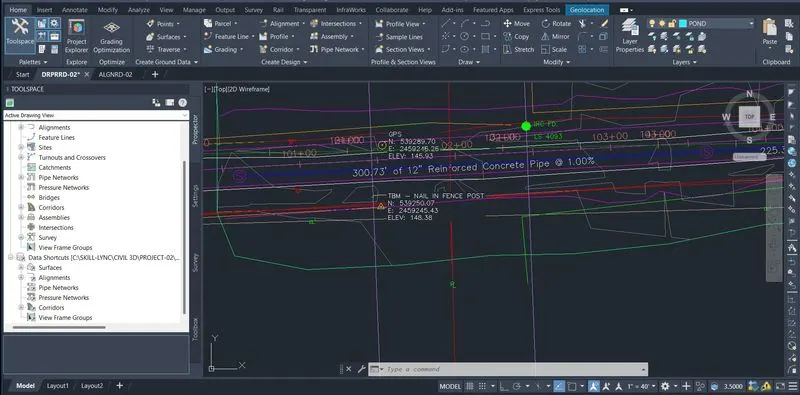
Click on home ribbon bar > alignment > Create alignment from network parts > select 1st and last structure > enter > create alignment option open > Select the option > ok > Create profile from surface > Select and upcoming options > Ok > place the profile > Profile created > Edit the properties for better representation.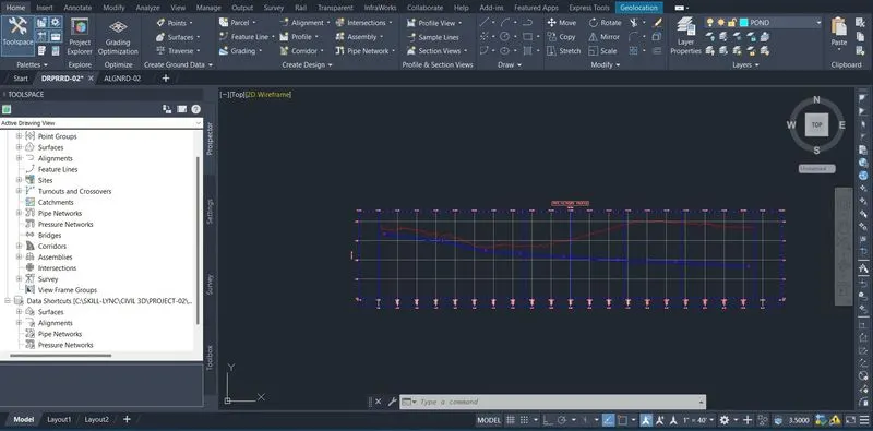
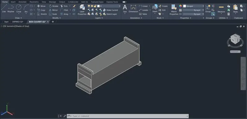
Open a new file named as " BOX CULVERT-02 " > Open drafting and annotation > Firstly, create front view with various command like "XL-enter-h-enter","XL-enter-v-enter","Line","Rectangle","Trim" > extrude the front view and substract the vacant position to allow drainage and with UCS System and line command BOX CULVERT is created.
STEP-08:
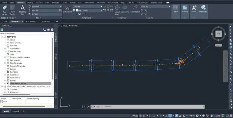
Open CLIPRD-02 file > Go to prospector tab > Right click on view frame groups > Create view frames > Set all option > View frames created.
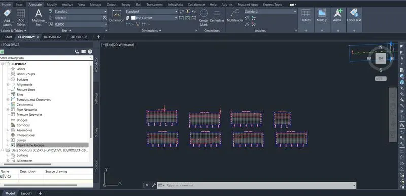
Click on profiles > Create profile from surface > All optios are selected > Draw in profile view > Profile view is selected for view frames.
Open RDXSRD-02 file > Create refrence of alignment and corridor > Click on section tab > Create sample lines > Select alignment > sample line tool box open > Select proper option > Sample line created.
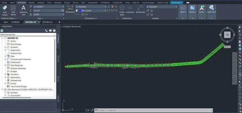
Again click on section tab > Create multiple section views > Select alignment > Select sample lines > edit section view name > Select all different option > Click on create section views > Section views created.
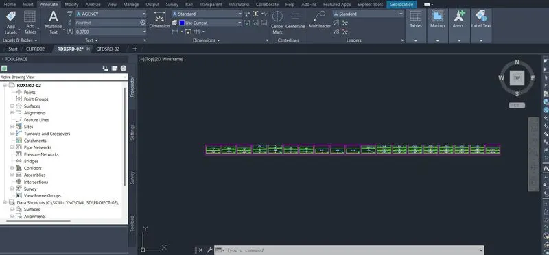
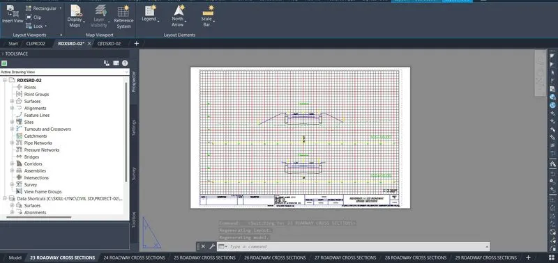
Click on output ribbon bar > Click on create section sheets > Select alignment > Select sample line group name > Select layouts name > Give the path > Create sheet > Sheet is created.
STEP-09 :
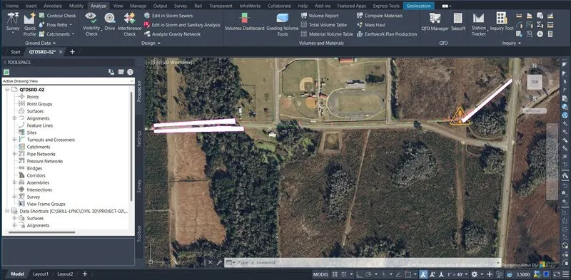
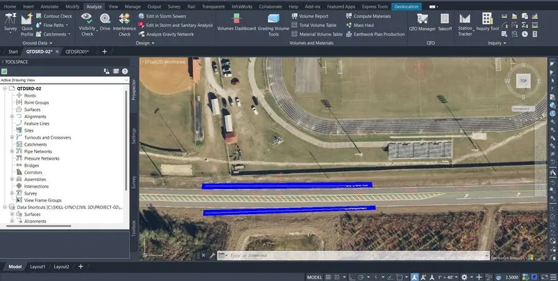
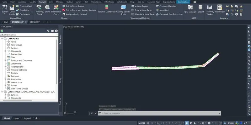
Create QTDSRD-02 file > Create refrence of alignment > Set the geolocation > add layer as Clearing and grabing > make it current layer > Set the area of clearing and grabing > Evaluate the quantity by qto manager in analyze ribbon bar.
Firstly, qto manager is set by click on file logo > Florida DOT > Agency.xml > Agency Categiries.xml > Ok.
All the items quantity can take off by above procedure.
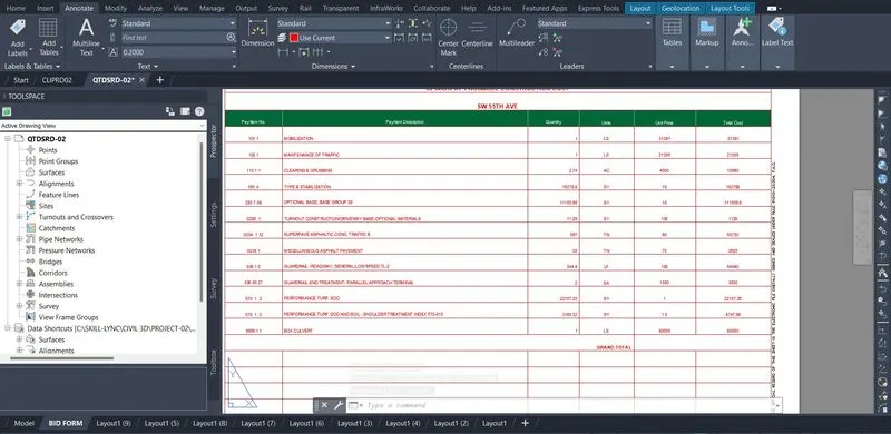
Set the title block to layout sheet > Annotate > Click on tables > Link data > Create a new excel data link (We have to create all excel data here) > Ok > Again click on tables > Click on tables logo > Insert option from data link (Select here files which one has to create > Ok.
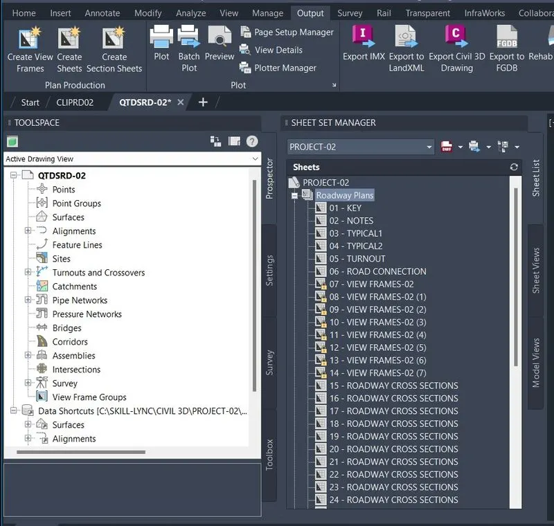
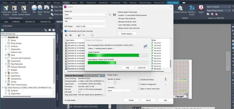
Open sheet set manager by ctrl-4 > Open given sheet set > Rename as PROJECT-02 > Right click on roadway plans > Import layout as sheet > Import sheet KEYSRD01, QTDSRD-02, PLPRRD-02, RDXSRD-02 > Rename and renumber it.
Click on file > Publish > Pdf preset:dwg to pdf > Publish.
STEP-10 :
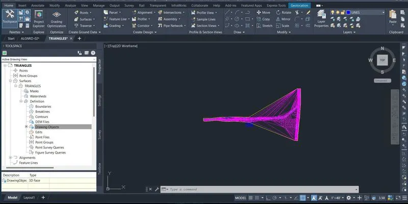
Open TRIANGLES files > Select one line > Right click and select similar > Click on surface > Name:TRIANGLES > Ok > Expand triangle > Expand defination > Right click on drawing object > Add > object type - 3d faces > Ok > Select the total figure > Enter > Surface created.