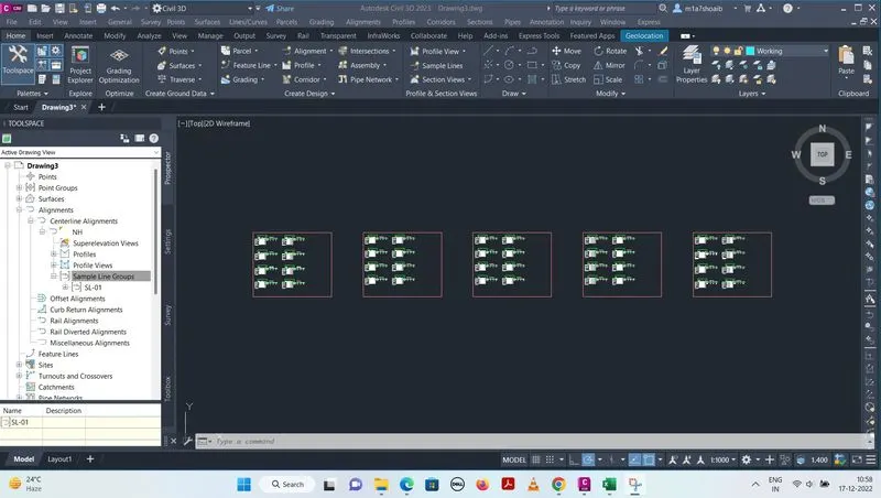
Project 2 - Lane National Highway Roadway Design in Civil 3D
Develope the road geometric design for 2lane NH concrete road with paved shoulder for 80kmph design speed from the provided data.
- Creation of surface.
- Alignment & profile design.
- Creation of assembly & subassembly.
- Corridor development.
- Section line & detail cross section.
Answer: 1. CREATION OF SURFACE :
a. BY LAND XML FILE :
- To create surface , Click Home Tab > Create ground data panel > Surface menu > Create surface
- The survey can be imported using that data
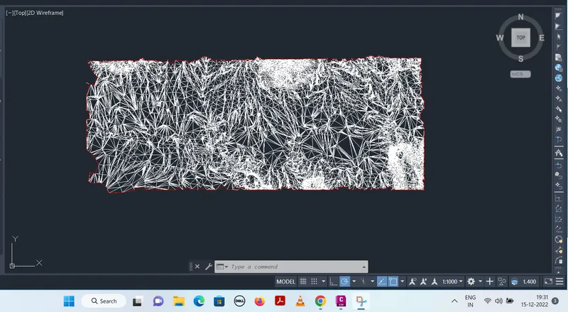
- Software generates automatic triangulation from nearby data points and generates 3D surface
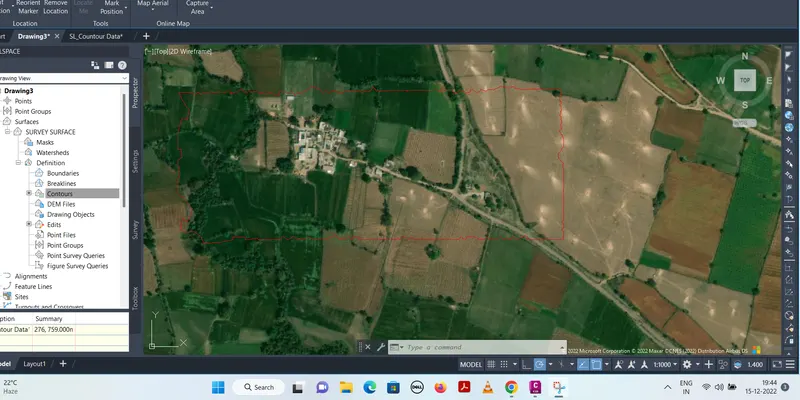
- Right click on triangulation, we can change the style to BORDER..
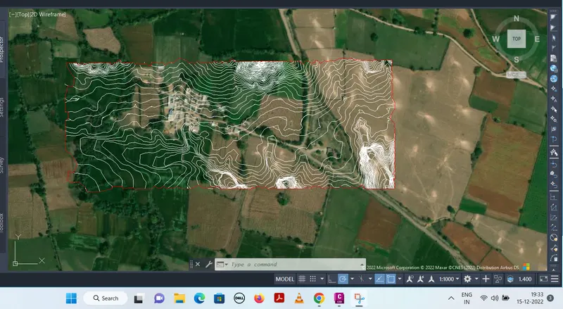
- From Geolocation , we can on the aerial view of the location
b. BY COUNTOUR LINE :
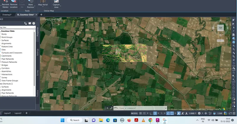
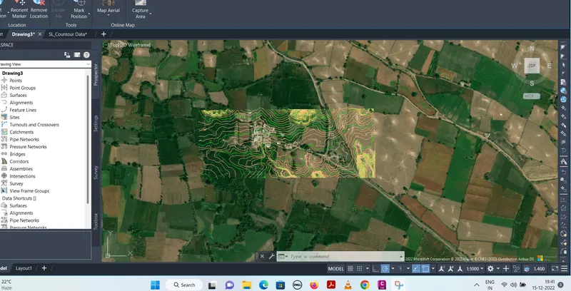
- To create surface, Click home tab > click open > open SL CONTOUR DATA > copy whole contour data from SL CONTOUR DATA > paste it with original coordinate in drawing 01
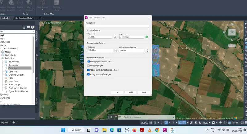
- Create survey surface and copy whole contour data
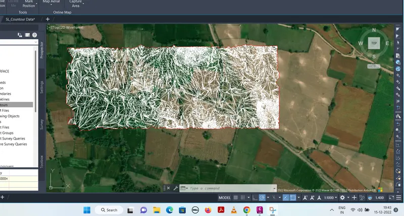
- Change the style with right click on line from triangulation to border
- Lay off all the contour for further design
2.a. ALIGNMENT DESIGN :
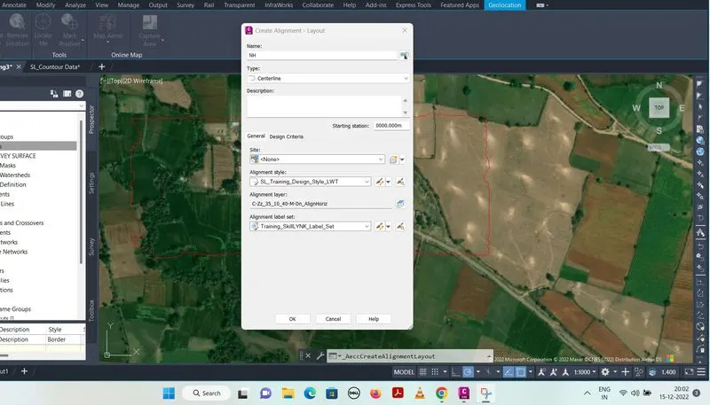
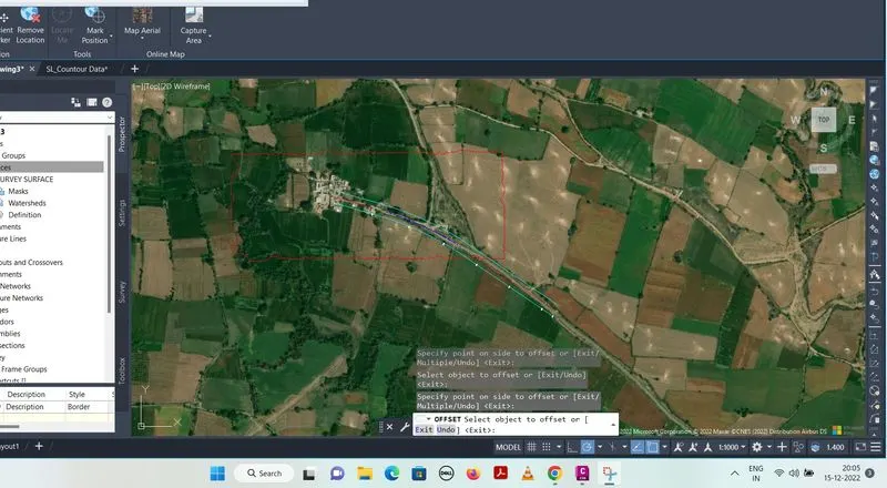
- To create alignment, click on alignment menu bar > Create alignment by layout > Modify name then ok > Alignment lay out tool will open
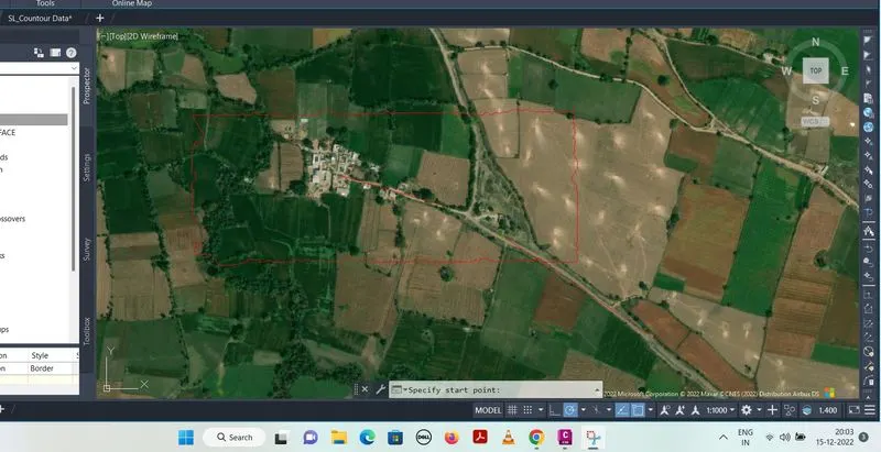
- Select, line (fixed line two points )
- Draw the first line and second line in interval
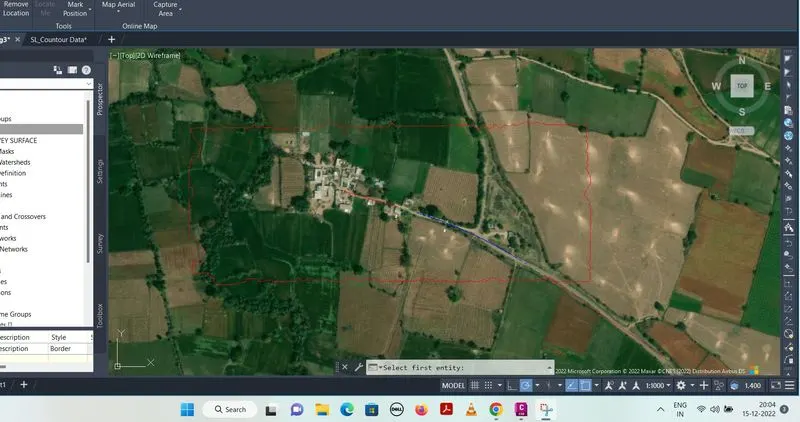
- Select spiral curve ( spiral- curve - spiral )
- Select two entities ( in which spiral curve will install )
- Create offset by command bar of 15 m interval in both side
2.b. PROFILE DESIGN :
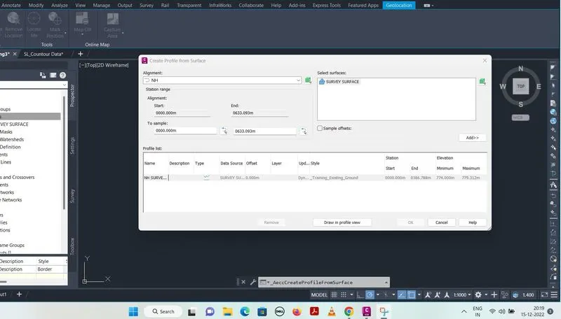
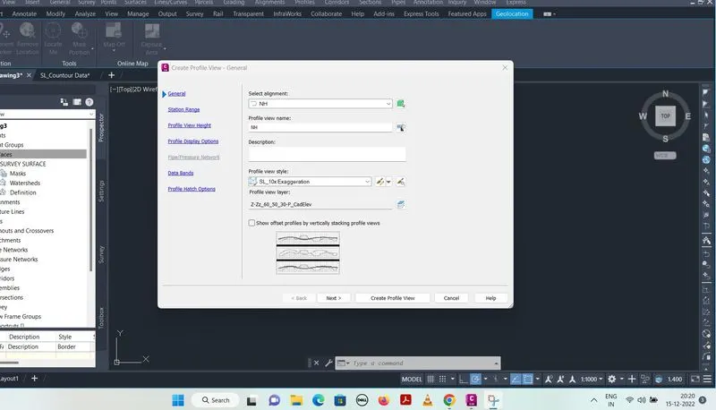
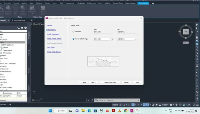
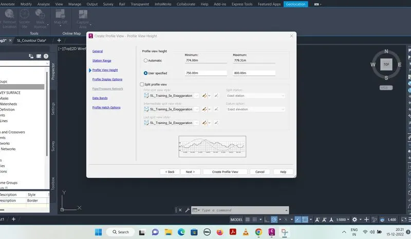
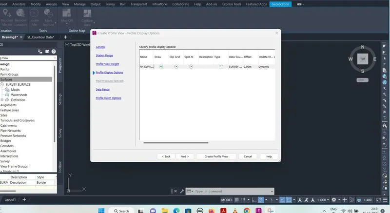
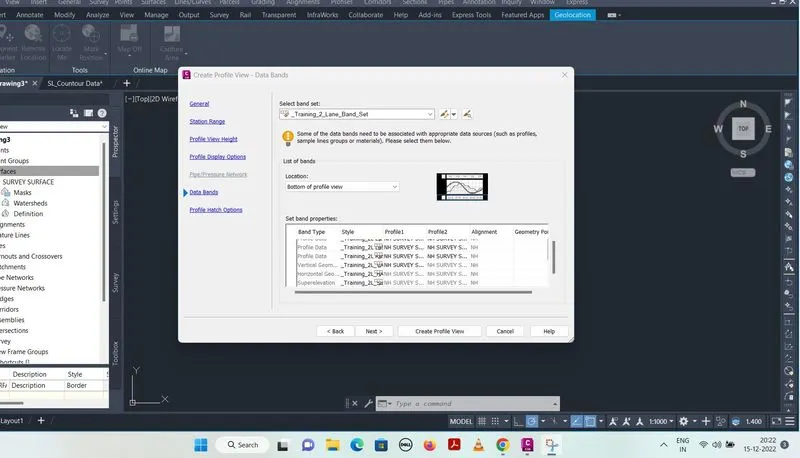
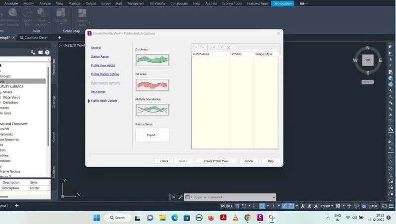
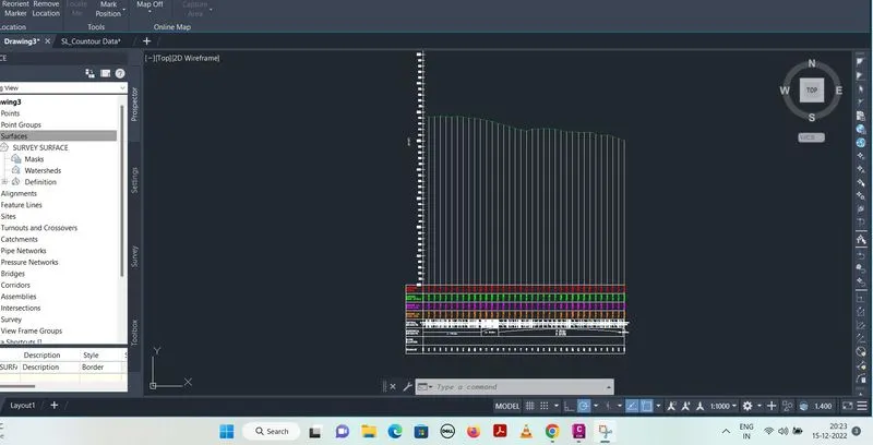
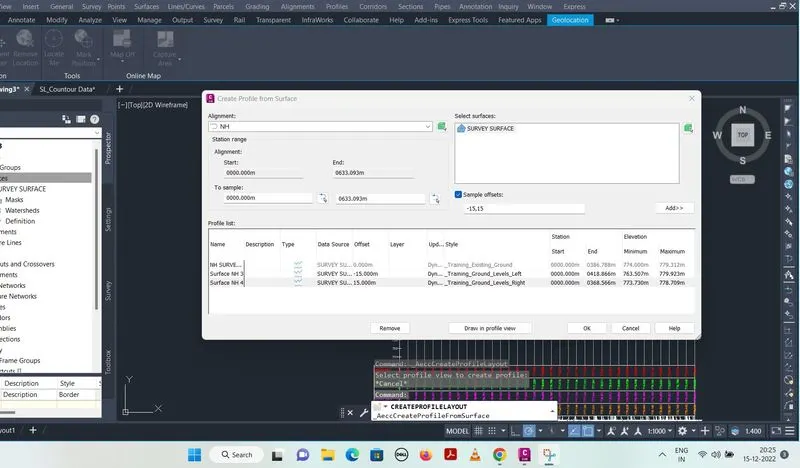
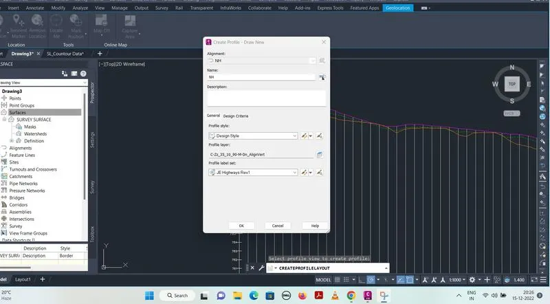
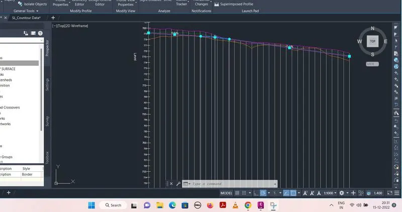
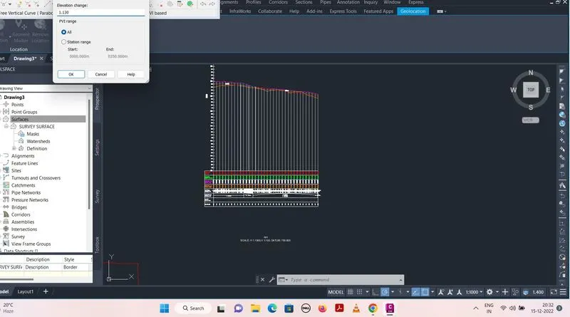
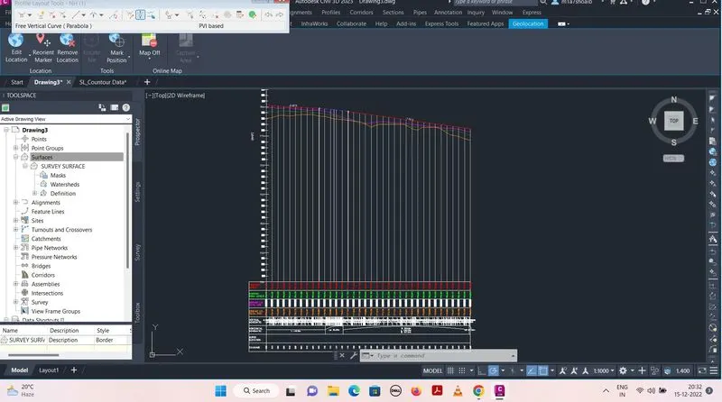
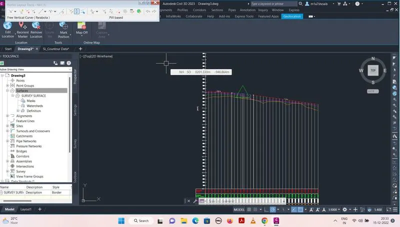
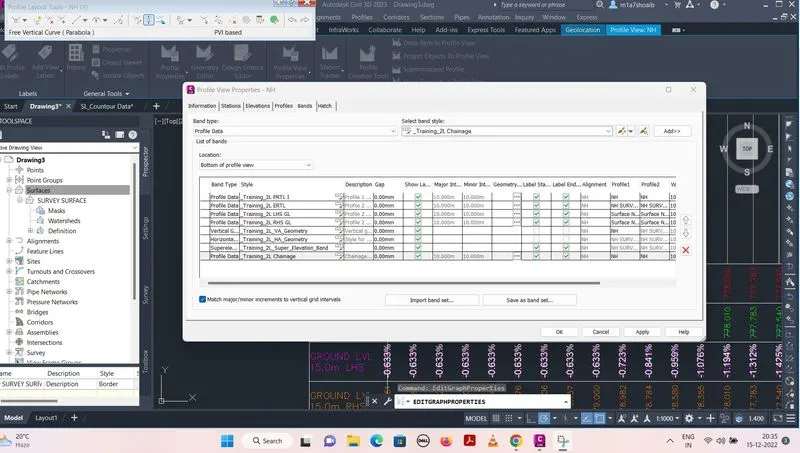
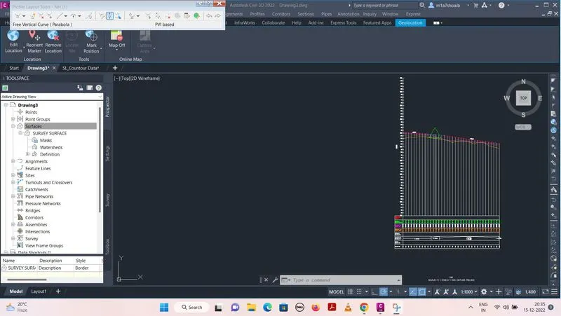
- To create profile, Click on profile menu bar > Create profile from surface > Select NH > Select Survey surface > Add > Draw in profile view > Modify profile view name > Profile view style (10x Exaggeration ) >set station range > Profile view height > Specific profile display option > Select band set > Profile hatched option
- Create profile from surface > Sample offset > Add
- Draw tangent from first point to last point
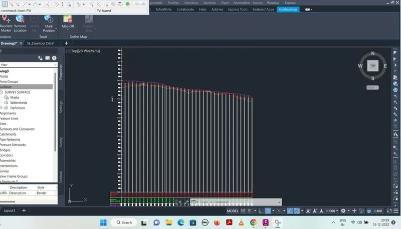
- Install PVI
- Install free vertical curve parabola
- Raise the PVI (for economy purpose )
- Change profile view properties
3. ASSEMBLIES AND SUBASSEMBLIES :
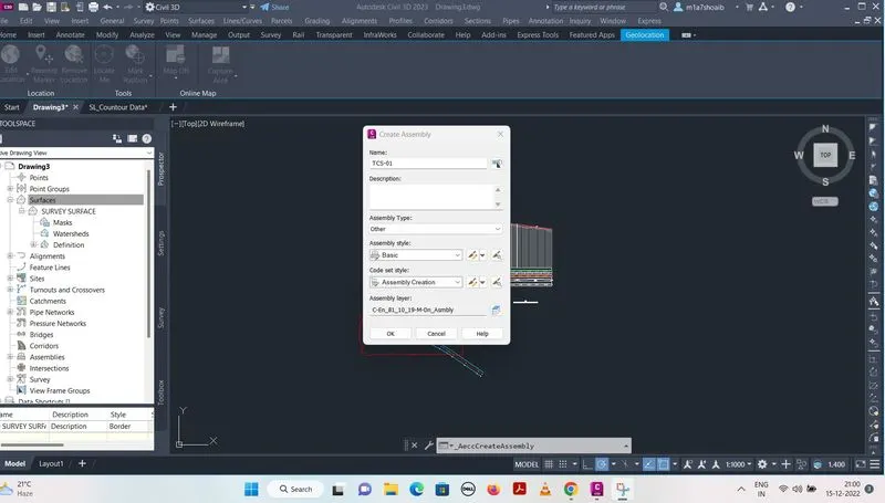
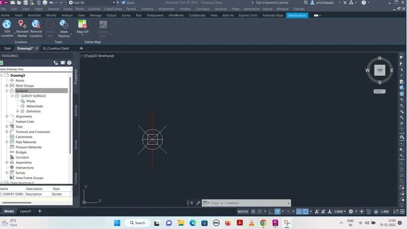
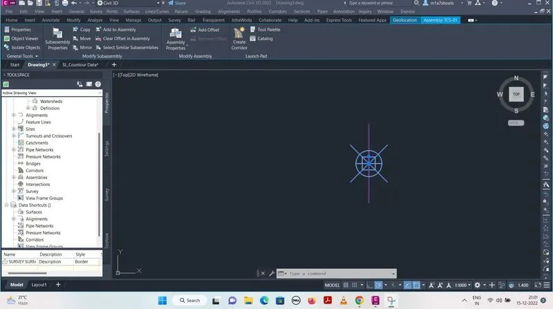
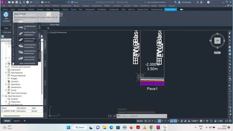
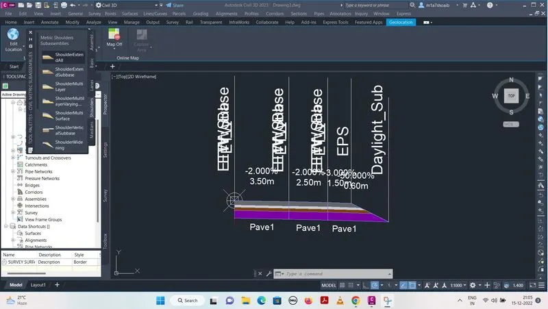
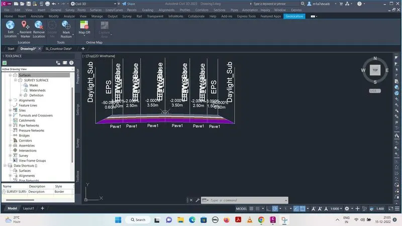
- To create assemblies, Click on corridor menu bar > Modify name > Place the assembly by clicking right > select the line of assembly > tool plates > lane > modify the assembly parameters > create paved shoulder > modify paved shoulder parameters > create earthen shoulder > modify the earthen shoulder parameters
- Create secondary road half section > modify its parameters > mirror it to the second side
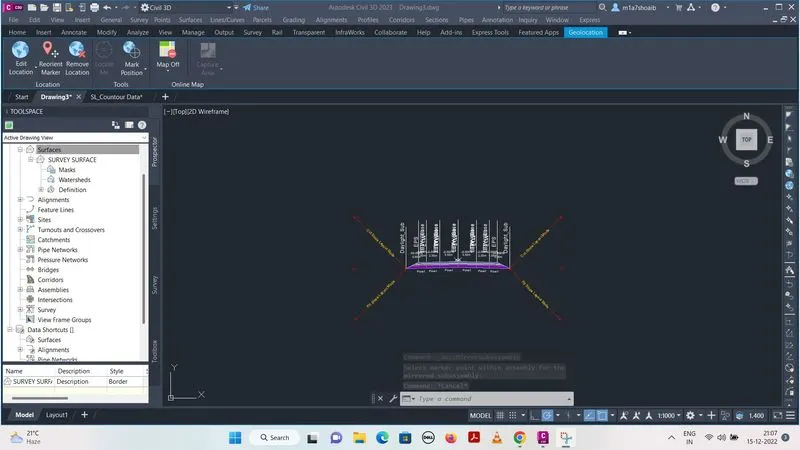
4. CORRIDOR :
- To create the corridor, click on corridor menu bar > Modify name > Modify assembly > Modify target surface
- Change the corridor properties
- Corridor will install
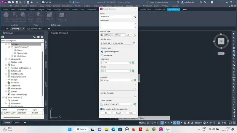
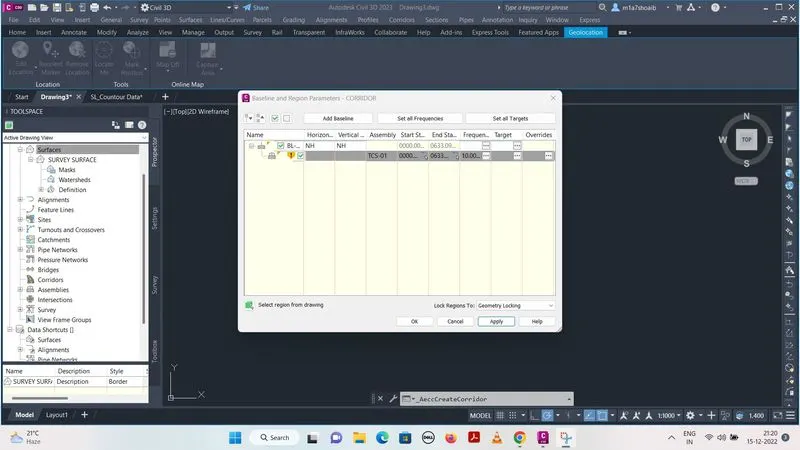
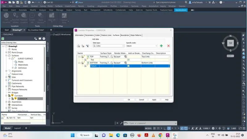
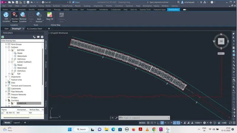
5.a. SECTION AND MATERIAL COMPUTATION :
- To create sample line, click on section menu bar > create sample line > modify name > modify properties > install sample lines
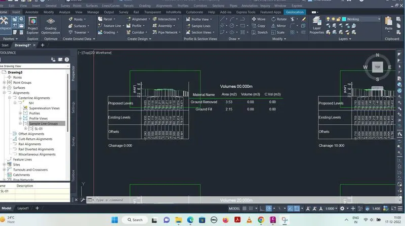
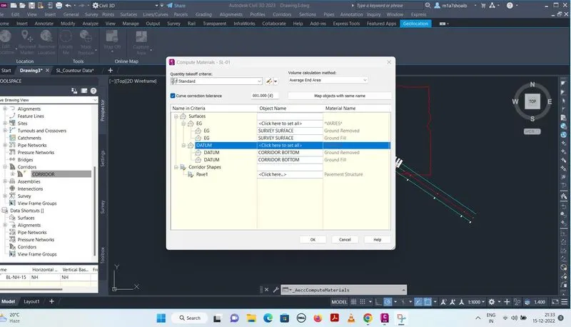
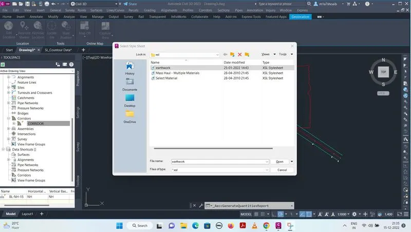
- To find material, click on material computation > modify properties > again click on material computation > modify properties > generate volume report (in excel sheet )
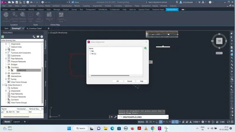
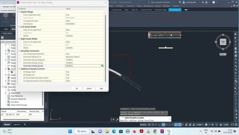
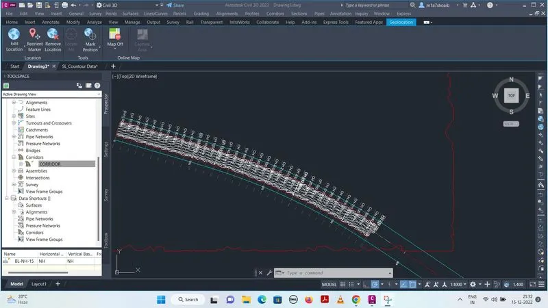
5.b. CROSS SECTION :
- To create cross section, Click on section menu bar > Create multiple section view >Modify general properties > Modify section placement > Modify offset range > Modify Elevation range > Modify section display option > Modify data bands > modify section views table > type (material) > add > Create section views .