Project - A project on design of road from a given topographic data
Key Highlights:
- Point creation and grouping them with the help of description.
- Preparation of surface and importance of breaklines.
- Horizontal alignment design and adding super elevation.
- Vertical profile design.
- Cross section template creation based on proposed conditions.
- Corridor modelling and extraction of finished surfaces.
- Cross sections production based on corridor modeling.
- Earthwork quantities and material quantities takeoff.
POINT CREATION :
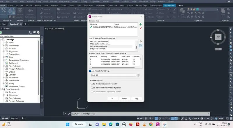
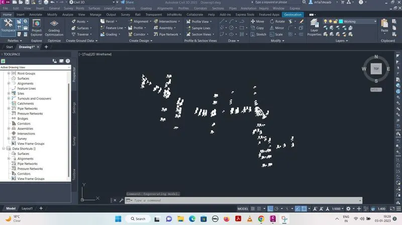
Click on point tab > Import / Export points > Import points > Select point survey (given) > Specify point format (PNEZD) > Add points to point group > Create group (ROAD-15) > Command (ZE enter).
SURFACE CREATION :
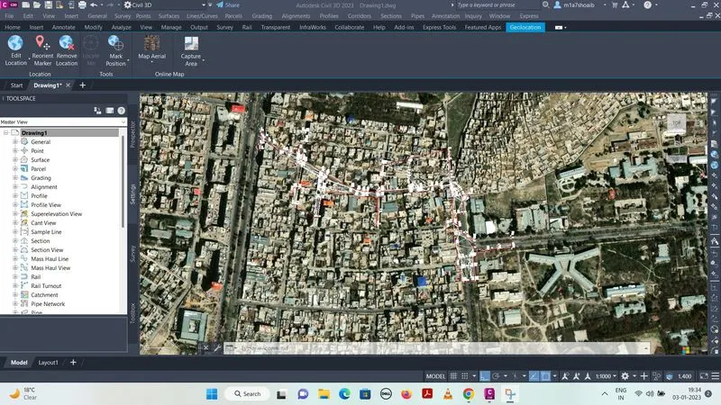
Click right on surfaces (toolspace) > Create surface > Name (SURVEY SURFACE) > Survey surface - Defination - point groups - ROAD 15 > Surface created.
ALIGNMENT CREATION :
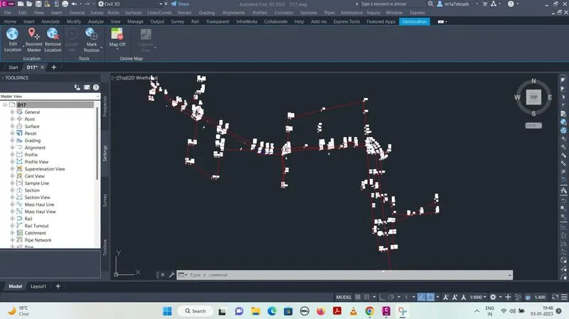
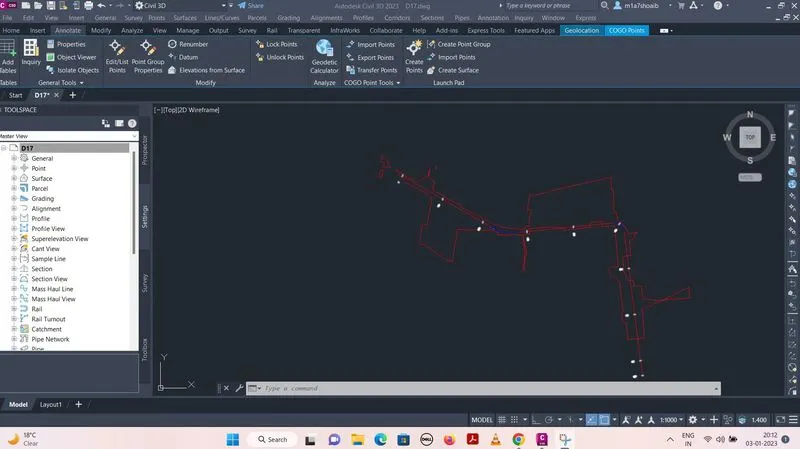
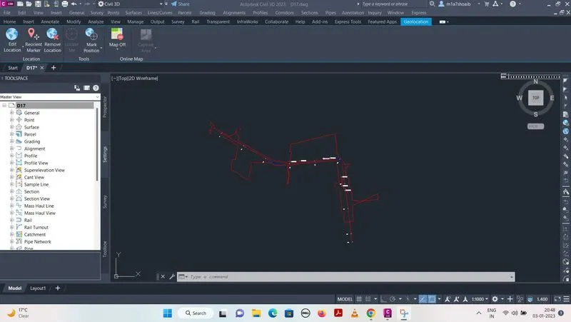
Click on alignment tab > Create alignment by layout > Open alignment layout tools > click on fixed line (Two points) > Selecting alignment > Free spiral-curve-spiral (Betwwen two entities) > Alignment created.
PROFILE CREATION :
Click on profile tab > Create profile from surface > Profile view name (NH) > Station range > Profile view height > Profile display options > Data bands > Create profile view > profile created.
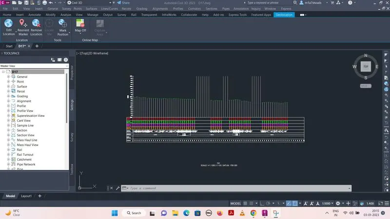
Due to less data some of points are not well defined so we have to add them for smooth profile.
Click on border line > Add lebels > Add points.
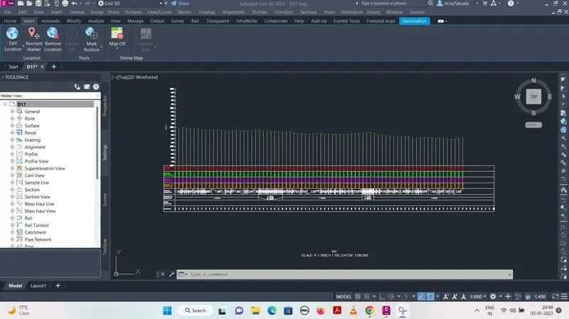
Click on profile tab again > Sample offset (-15,15) > Add .
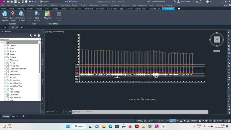
As offset is seeing uneveness due to less wide data.
Click on profle tab > Create profile by layout > Profile layout tool open > Draw tangent > Raised the tangent > Correct the profile view properties.
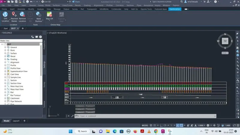
ATTAINMENT OF SUPER-ELEVATION :
Click on alignment > Super elevation tab > Calculate superelevation now > Undivided crown > Correct different option > Superelevation installed.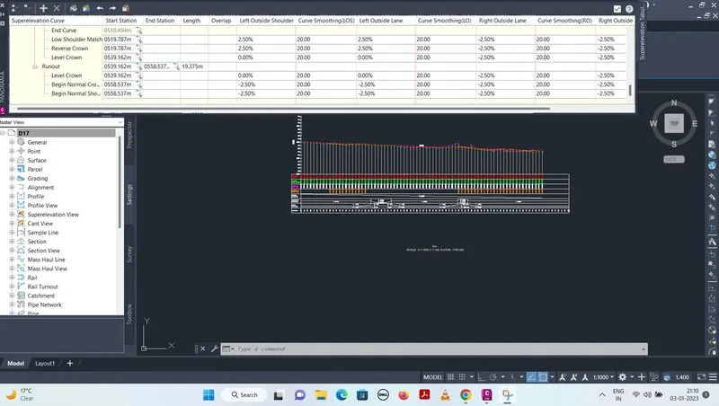
Click on alignment > Right click > Edit alignment lebels > Install station.
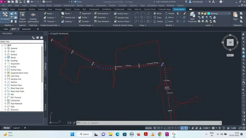
CREATION OF ASSEMBLIES AND SUB-ASSEMBLIES :
Click on file > Open given assemblies > Copy in drawing > Take symmetric assembly > Copy and rename assemblies (TCS-01, TCS-02) > Modify assemblies.
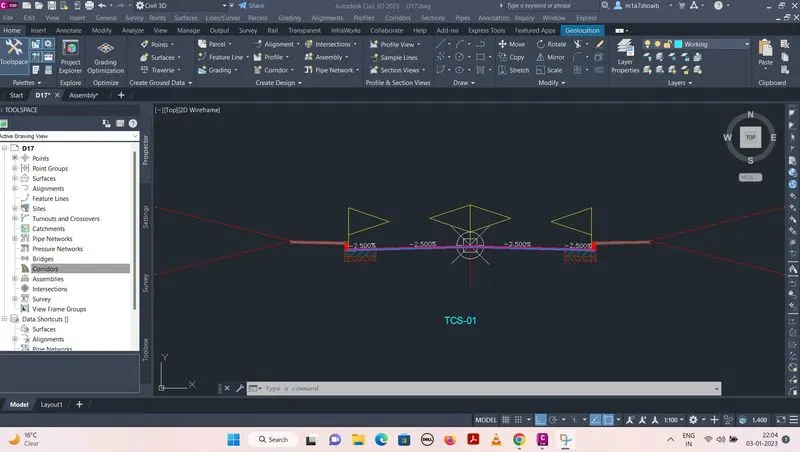
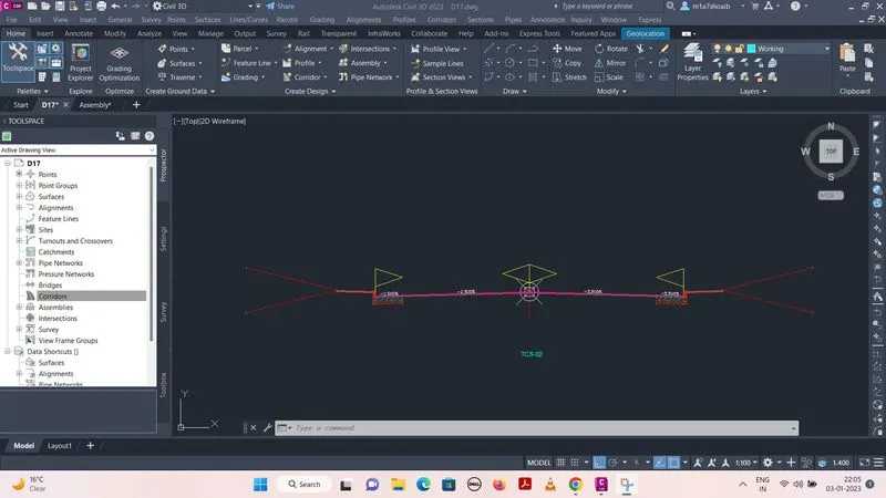
CREATION OF CORRIDOR :
Click on corridor tab > Create corridor > Name (corridor) > Alignment (NH) > Profile (NH) > Assembly (NH) > Target surface (SURVEY SURFACE) > Ok and corridor created.
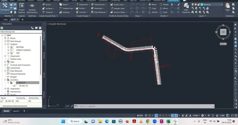
There are two corridor (TCS-01,TCS-02), modify the corridor from 0 to 558 and 558 to 750 m.
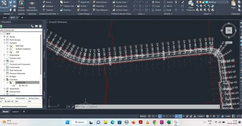
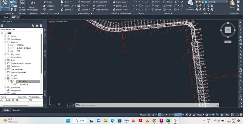
CREATION OF SAMPLE LINE :
Click on section tab > Create sample lines > Install sample line at each 10 m interval.
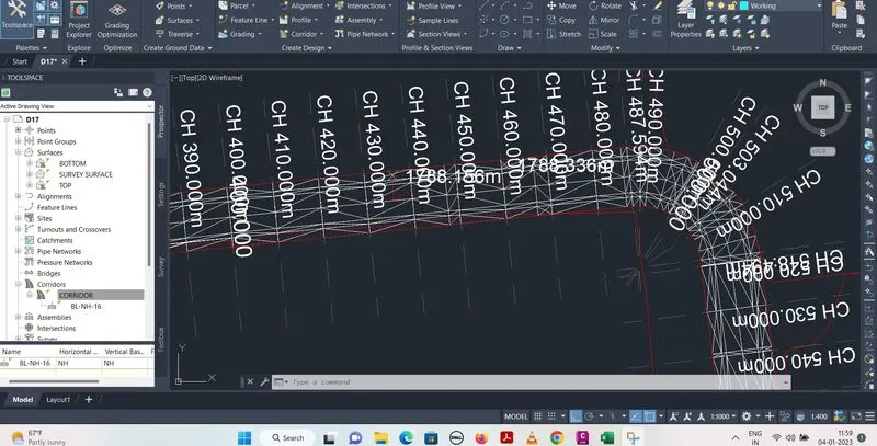
Click on compute material > Modify options > Again compute material and modify > Generate volume report in excel sheet.
CREATION OF MULTIPLE SECTION VIEWS :
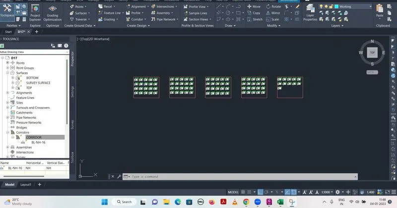
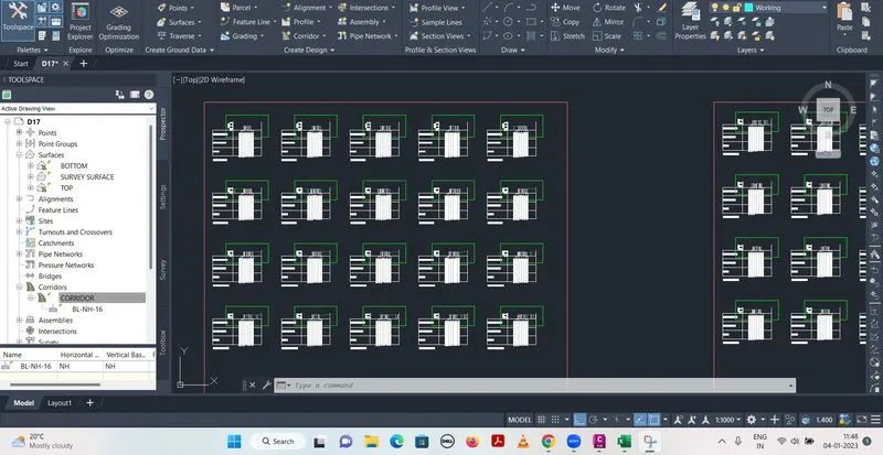
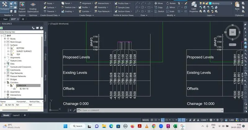
Click on section tab > Create multiple section views > Modify options > Multiple section views created.