Week 6 Challenge
AIM : PIPE LOAD ON BRIDGES AND ANALYSIS OF BRIDGE IN STAADPRO
INTRODUCTION :
- In this challenge i have to calcuate pipe loads on bridges . Bridge is loacated at bank of Narmada River
- Due to some improper photos are given i assumed some values and sections are not as per photos
- Some values are taken from the google.
Given :
- Span of the bridge = 24m
- width of the bridge 3m
- Height of the truss = 2.5m
- Height of pier =5m asumed
- Dia of pipe =
600NBDI = 217.19 Kg/m load as per class K9 for pipe length 5.5m
200NBDI = 45.28 Kg/m Load as per class 9 for pipe length 5.5m
ASUMPTIONS :
- Height of pier = 5m
- top and bottom chord = ISMB350
- Vertical and strut = ISMC300
- Diagonal and top lateral bracing = ISA 90X90X8
MANUAL CALCULATION FOR THE LOADING :
1. For 600NBDI pipe of class K9 in kg/m
load for 5.5m length = 217.19 kg/m
for 24m length = 24/5.5 = 4.36
load = 217.19 x 4.36 = 946.94kg/m
to aplly this load on bridge i have to convert this load into kn/m
1kg/m = 0.00981 kn/m
Load = 946.94 x 0.00981 = 9.28kn/m
Self weight of 600NBDI pipe = 9.28kn/m
- LIVE LOAD IN 600NBDI PIPE = AREA X UNIT WEIGHT OF WATER
- = `(PIE/4)*(0.6*0.6)` x 10
- = 2.82 KN/M
- `TOTAL WEIGHT IN 600NBDI PIPE = SELF WEIGHT + LIVE LOAD`
- = 9.28 + 2.82
- `nbsp; = 12.1 KN/`
2. For 200NBDI pipe of Class K9 for 5.5m length
For 600NBDI pipe of class K9 in kg/m
load for 5.5m length = 45.28 kg/m
for 24m length = 24/5.5 = 4.36
load =42.28 x 4.36 = 197.42kg/m
to aplly this load on bridge i have to convert this load into kn/m
1kg/m = 0.00981 kn/m
Load = 197.42 x 0.00981 = 1.93kn/m
Self weight of 600NBDI pipe = 1.93kn/m
- LIVE LOAD IN 600NBDI PIPE = AREA X UNIT WEIGHT OF WATER
- = `(PIE/4)*(0.2*0.2)` x 10`
- `nbsp; = 0.44 KN/M`
- `TOTAL WEIGHT IN 600NBDI PIPE = SELF WEIGHT + LIVE LOAD`
- `nbsp; = 1.93 + 0.44`
- `nbsp; = 2.33KN/`
PROCEDURE TO CREATE MODEL :
STEP 1: TRUSS CREATION :
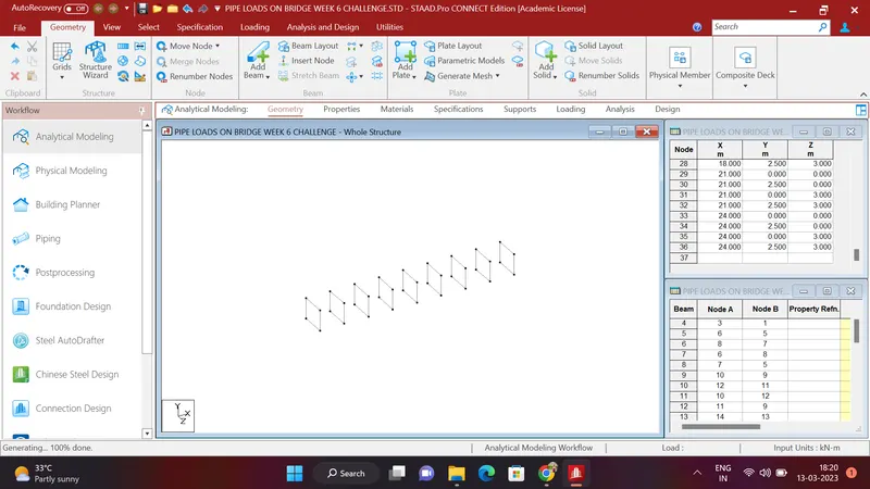
- In the first step i created a node at 0,0,0 and by using traslational repeat copied this node at y anis and created beam between this two nodes. Selected the created beam and by using translational repeat copied this beam in Z direction and conected upper and bottom nodes by adding beams in it .
- The squre of beam is created of size 3m width and 2.5m height and as per the drawing given in the question and this squre is copied in the X direction by using translational repeat of distance 3m of 7 steps such as 24m span we are creating . then structure looks like below photo
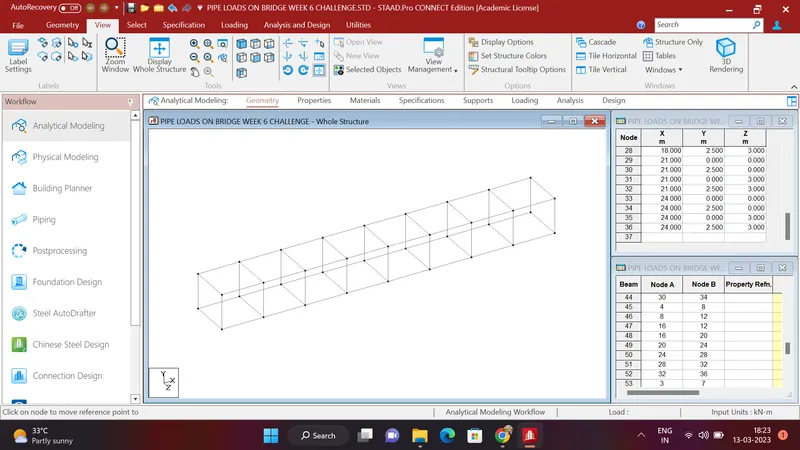
- After that the nodes are joined and square truss is created , beams are created in bottom and upper part horizontally then structure will look like this
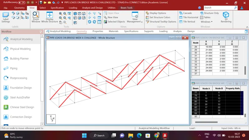
- Diagonal sections are created as per the drawing and jpoined the nodes as per drawing
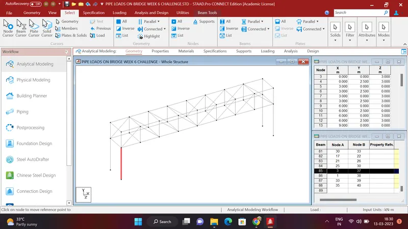
- Piers are created of 5m height
- After Fixed Suports are cetaed and assigned to the bottom nodes of the all the pier
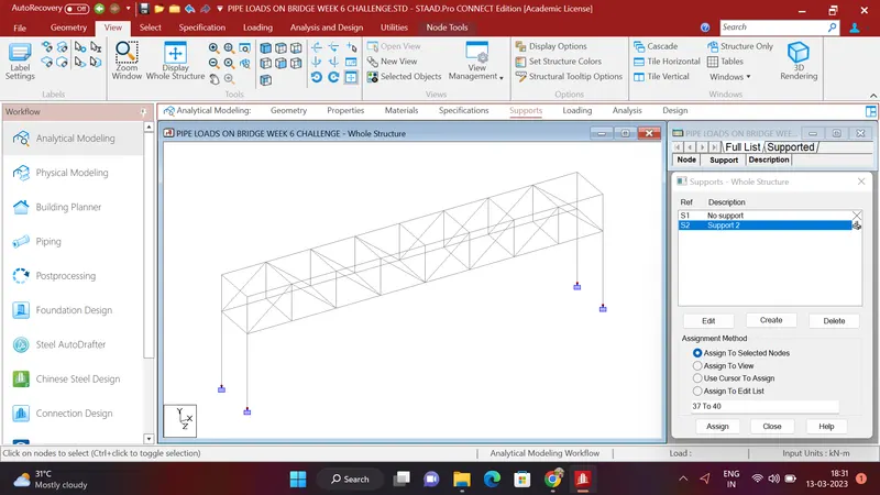
- Clicked on the properties and created a following :
- ISMB350 STEEL
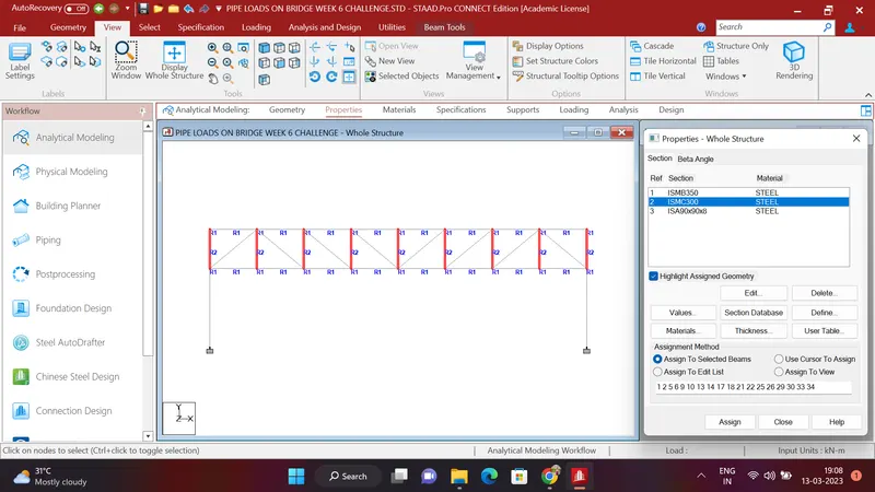
- ISMC300 STEEL
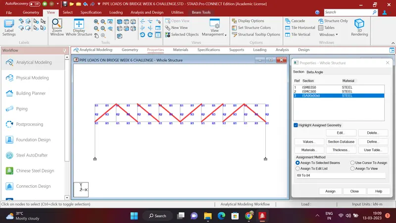
- ISA90X90X8 STEEL
- CIR 1.5M DIA CONCRETE
- The created properties are assigned as follow
- ISMB350 : this proprty is given to the top and bottom chord as follow
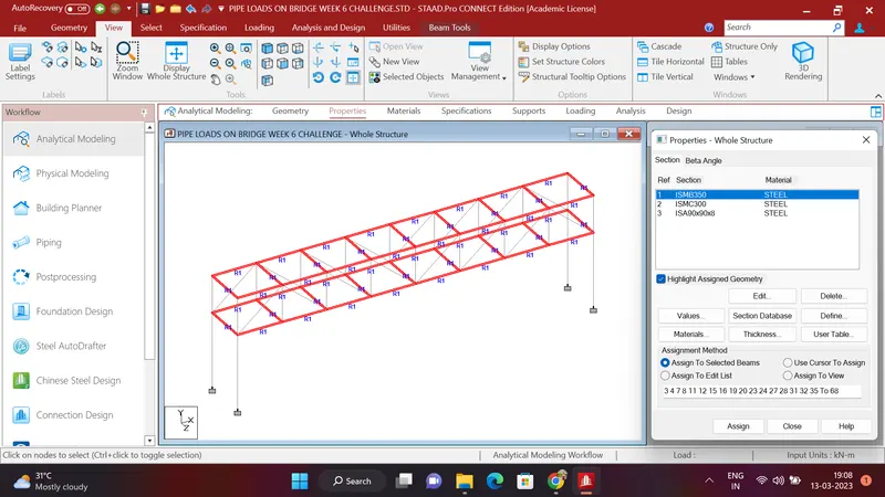
b. ISMC300 : this property is given to the verticle member
c. ISA90X90X8 : this property is given to the diagonal bracing
d. CIR 1.5M DIA CONCRETE : this property is asigned to the piers
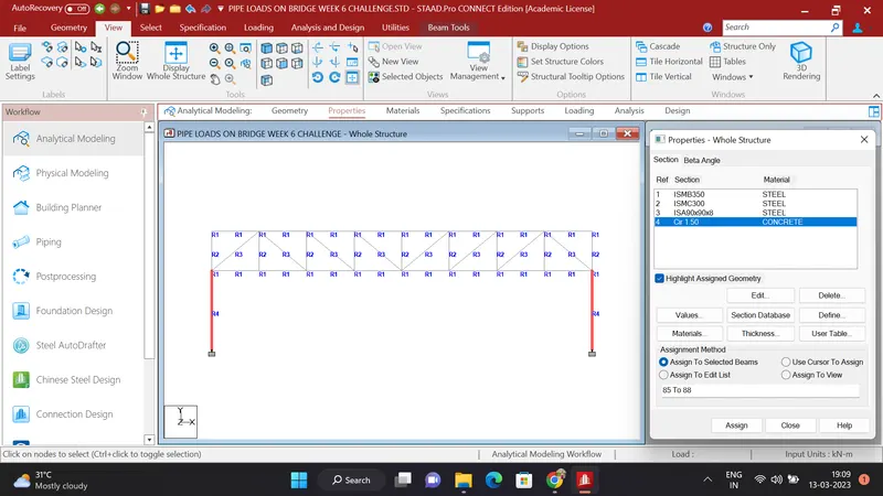
e. As per the question to give the pipe load on bridge the 2 Dummy girders are created of 0.1mX0.1m size are as below
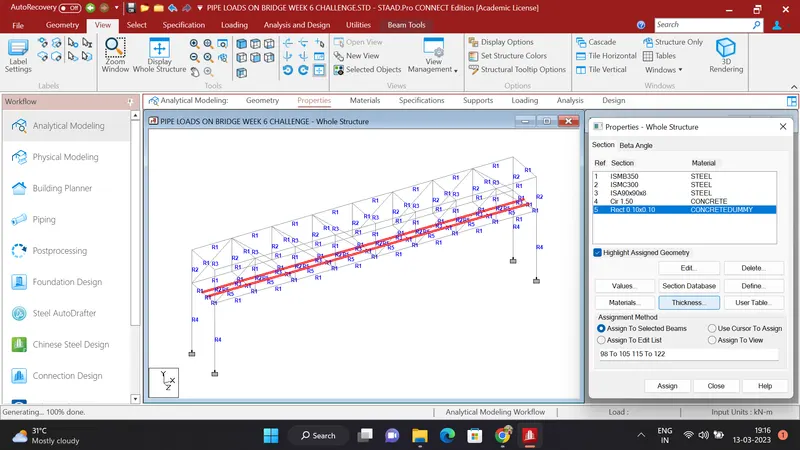
- Now our geometry is created and properties and supports are given and our structure will looks like this
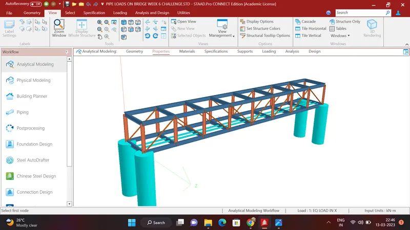
STEP 2: LOADINGS :
GIVEN DATA :
The bridge is located in the banks of river narmada. Assume that the narmada river is flowing in the jabalpur city in madhya pradesh
thiats why i have to give seiesmic load and pipe load on the bridge
- SEISMIC LOAD :
- To create a seismic load click on Loading option
- Click on Definitions - Seismic definition - generate -
- select city=Jabalpur
- select Response reduction factor = Steel building with special moment resisting and add self weight =1
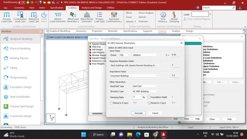
- Click on load cases details- add - names as EQ in X,Y and Z direction and add seismic load as IS1893 part 6 load in all direction
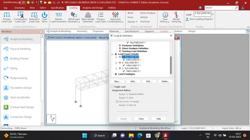
- After all this operation seismic load is created successfully .
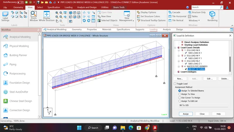
2. PIPE LOAD :
- Click on load case details
- add load case named as PIPE LOAD 600NBDI - ADD - MEMBER LOAD - UNIFORM LOAD = -12.1Kn/m and assign this load to the dummy beam shown as figure
- Click onload case details and add load case named as PIPE LOAD 200NBDI - ADD - MEMBER LOAD - UNIFORM LOAD - 2.33kn/m and assign this load to the another dummy beam as shown in figure
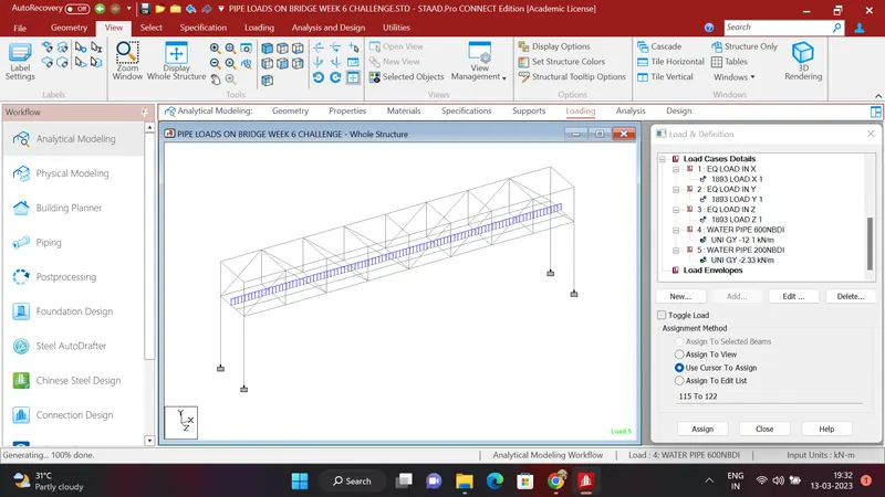
- Now the load is added successfully to the dummy beams
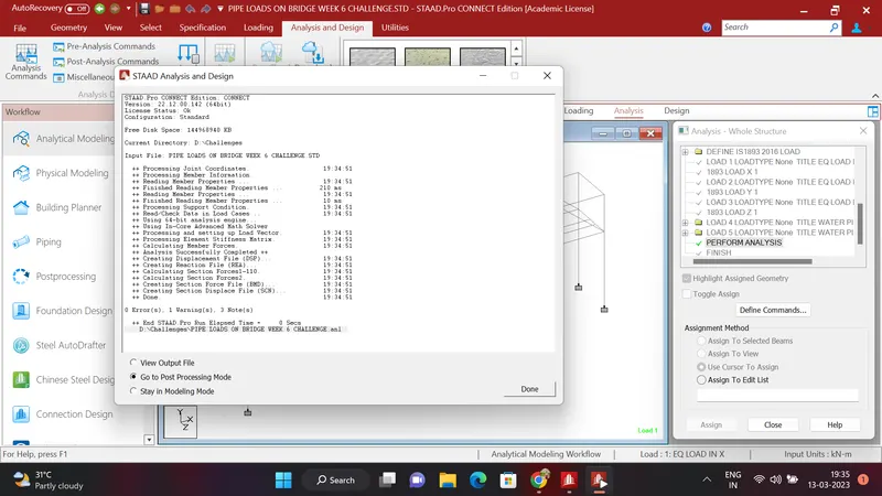
STEP 3 : ANALYSIS :
- Click on analysis and design run the file and see the deflection of the bridge
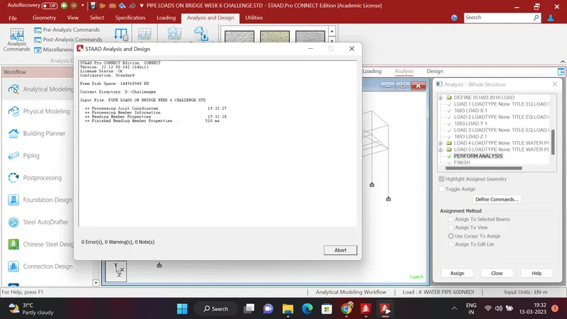
- After running the file go to postprocessing mode and see the results
STEP 4 : RESULTS
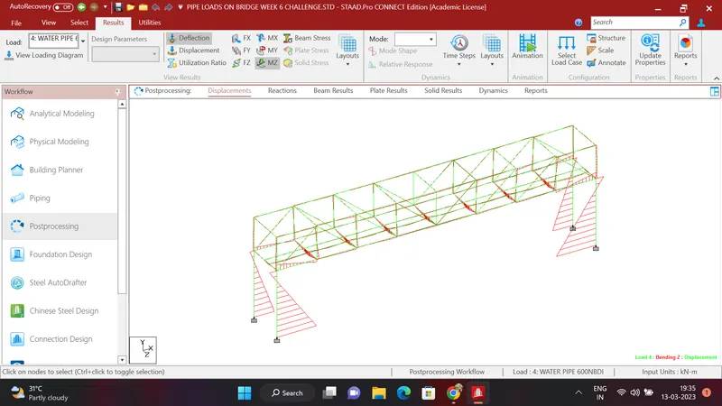
- DESPLACEMENT :
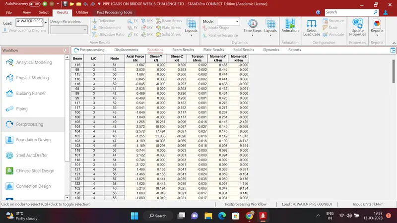
2. REACTIONS :
3.SFD AND BMD DIAGRAM OF ENTIRE BRIDGE :
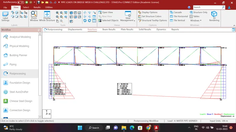
FINAL RESULTS : THE SHEAR FORCE AND BENDING MOMENTS IS DIFFERENT IN DIFFERENT SECTIONS
THE STAADPRO FILE IS ATTACHED BELOW
THANK YOU .