Week 6 Challenge
Structural Systems of Industrial structures
Introduction:
In this Structural Systems of Industrial Structures, here to be solve the design problems for chequered plates, RC Decking slab, and also draw the lateral and Gravity load resisting system in the bracing system with states its different types in this challenge.
Question No: 1. Chequered Plate design
Design a chequered plate to carry a uniformly distributed Factored live load of 15 kN/m2. Consider the plate is spanned with dimension of 1200 mm x 5000 mm with all edges fixed. (Refer Roarks chart table 11.4)
Aim:
To be design a chequered plate by using the given data in the problem.
Given Data:
UDL = 15 KN /m2
Dimensions = 1200 mm x 5000 mm
All Edges are fixed.
Procedure:
We know that, Steel Density = 78.5 KN/m3
Assume plate thickness = 10 mm = 0.01 m
Self-weight of the plate = 0.01 x 78.5 = 0.785 KN/m2
As per Refer Roarks chart table 11.4
Allowable deflection of Thickness of the Plate (y) = 10 / 2 = 5 mm.
Stress at Centre Point:
σ = β2qb2 / t2
a / b = 5000 / 1200 = 4.167
Therefore, β1 = 0.5000, β2 = 0.2500, α = 0.0284
σ = 0.2500 x 15 x 1.22 / 0.012
= 54000 KN/m2
σ = 54 N/mm2
Stress at center of Long edge Point:
σmax = -β1qb2 / t2
a / b = 5000 / 1200 = 4.167
Therefore, β1 = 0.5000, β2 = 0.2500, α = 0.0284
σmax = -0.5000 x 15 x 1.22 / 0.012
= -108000 KN/m2
σmax = -108 N/mm2
Therefore, here it is a safe.
Deflection at centre:
ymax = αqb4 / Et3
= 0.0284 x 15 x 1.24 / (2 x 105 x 0.013)
ymax = 4.42 mm
Result:
- Stress at centre Point σ = 54 N/mm2
- Stress at center of Long edge point σmax = -108 N/mm2
- Deflection at centre point ymax = 4.42 mm
Conclusion:
Here the value of the maximum deflection (ymax) is lesser than the Allowable deflection (y). So, this chequered plate is safe to carry the load.
Question No: 2. Design of Decking slab.
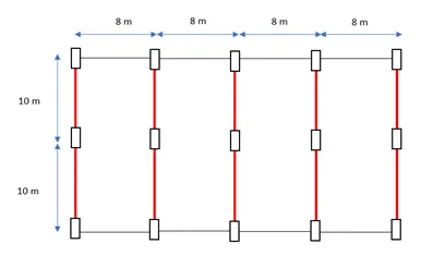
Design thickness of RC slab required to carry Dead load of 5 kN/m2 & Live Load of 8 kN/m2 for a mezzanine floor in an Industrial structure with plan as shown below. Provide optimum spacing of the secondary beam and also choose the decking sheet profile to be used. Neglect the composite action of decking sheet and RC slab. Decking sheet is provided only for formwork purpose.
Aim:
To be design the RC Decking slab by using the given load factors and given other data.
Given Data:
Dead Load = 5 KN/m2
Live Load = 8 KN/m2
LX = 8 m
LY = 10 m
Procedure:
Load Calculation:
Total Load = DL + LL = 5 + 8 = 13 KN/m
Factored Load = 1.5 x 13 = 19.5 KN/m
Depth of Slab:
We considered, that
Pt = 0.4 %, Fs = 240 N/mm2, Mf = 1.3
l/d = 20 x Mf
8000/ d = 20 x 1.3
d = 310 mm.
D = 310 + 20 + 10/2
D = 335 mm
Effective of Span:
Effective of Span = Clear Span + Effective Depth
Ef = 8000 + 310
Ef = 8310 mm
Lx = 8310 mm, Ly = 10310 mm
Bending Moment:
Ly / Lx = 1.25; Lx = 0.075
Mwx = αx wu (Lx)2 = 100.9 KN/m
Mwy = αy wu (Lx)2 = 75.4 KN/m
Mu (lim) = 0.138 x Fcd x b x d2
100.9 x 106 = 0.138 x 25 x 1000 x d2
Dreq = 171 mm
Reinforcement:
Along Shorter Span Pt = 0.2%
As = (0.2 / 100) x 1000 x 310
As = 620 mm2
For 10mm Diameter bars
Spacing = (78.3 / 620) x 100
S = 120 mm
As (prov) = 654.41 mm2
As (min) = (0.12/100) x 1000 x 33.5
As (min) = 402 mm2
As (min) < As (prov)
Pt = 0.152 %
As = (0.152 / 100) x 1000 x 310
As = 471.2 mm2
For 8 mm Diameter bars
Spacing = (50.26 / 471.2) x 1000
S = 120 mm
As (prov) = 502.6 mm2
As (min) = (0.152/100) x 1000 x 335
As (min) = 500 mm2
As (min) < As (prov)
Result:
For both 8 mm and 10 mm Diameter of bars are As (min) < As (prov). So the design is safe.
Conclusion:
Thus the design of the RC decking slab has been found out in the problem using the given load factor and slab length data.
Question No: 3. Lateral Load resisting system & Gravity Load resisting system
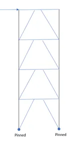
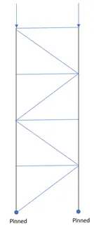
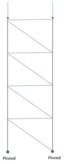
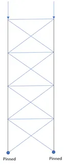
Draw the load path and identify the Axial force type in different type of bracing system below to resist horizontal shear & gravity load. Also state the type of bracing system.
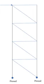
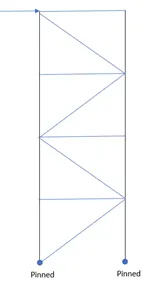
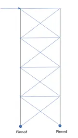
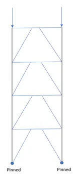
Aim:
To be Draw the load path and identify the Axial force type in different type of bracing system below to resist horizontal shear & gravity load. Also state the type of bracing system.
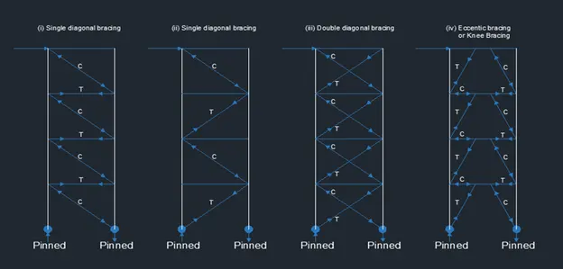
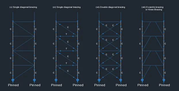
Drawing of the load path and acted axial force type in different type of bracing system
Bracing System:
In a multi-storey building , the beams and columns are generally arranged in an orthogonal pattern in both elevation and on plan. In a braced frame building, the resistance to horizontal forces is provided by two orthogonal bracing systems:
Types of Bracing Systems
Majorly Bracing systems are classified as:
- Horizontal Bracing System
- Vertical Bracing System
Horizontal Bracing System
This consists of bracing at each floor in the horizontal planes thus providing load paths so that the horizontal forces can be transferred to the planes of vertical bracing.
The horizontal bracing system is too divided into two major types namely:
- Diaphragms and
- Discrete triangulated bracing
Some floor systems provide perfect horizontal diaphragm while others like precast concrete slabs require specific measures. It can be understood by the example of steelwork and precast concrete slab as these must be joint together properly to avoid relative movements.
Discrete triangulated bracing is taken into consideration when the floor system cannot be used as a horizontal bracing system.
Vertical Bracing System
In vertical planes, there are bracing between column lines which provide load paths that are used to transfer horizontal forces to ground level. This system aims to transfer horizontal loads to the foundations and withstanding the overall sway of the structure. These are the bracings placed between two lines of columns.
It can also be studied in two types namely:
- Cross bracing and
- Single diagonal.
Cross bracing is slenderly withstanding tension forces only and not compression forces, it also provides necessary lateral stability depending on the direction of loading.
Unlike Cross bracing, Single diagonal bracing is designed to resist both tension forces and compression forces. In this, diagonal structural members are inserted into rectangular areas of a structural frame which is good for stabilization of the frame. For fulfilling the requirement of a comparatively efficient system, bracing elements are placed at nearly 45 degrees. This arrangement is strong and compact.
Type of bracing systems based on Shapes and arrangements
Depending upon the various requirements in building systems the major bracings are classified in to six following types
- Forward bracings
- Backward bracings
- V type bracings
- Inverted V type bracings
- X type bracings and
- K type bracings
Forward bracing systems
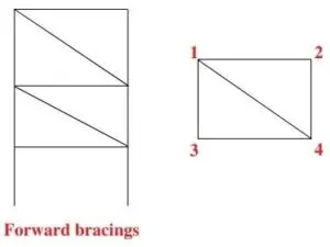
The forward bracing systems are comes under the diagonal bracings type, in this the bracing system is connected in the diagonal direction to the end points. See the forward bracing system model in the below specified figure which is consisting of four end points namely 1, 2, 3 and 4. The steel bracing system is joined from the 1st end to the 4th end point. The forward bracing system under the category of diagonal type is generally helps to reduce the X direction or Y direction storey drift values under the lateral loading actions (wind load and seismic load values).
Backward bracing systems
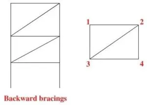
The backwards bracing system is the second type which is comes under the diagonal bracings. The basic concept is similar to that of the forward bracing system but the storey drift value is decreases in the opposite direction of forward bracings. See the complete backward bracings type in the below figure which is again consisting of four end points for the bay frame. The bracing system is connected to the 2nd and 3rd end points. This type of bracings system is helps in decreasing the storey drift values in –X direction or –Y direction to the building structure under the lateral loading action.
V type bracing system
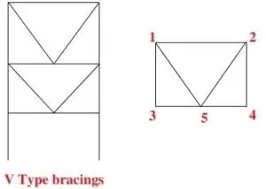
The V type bracing system is comes under third type which is comes under the vertical bracings system. The main objective of this case is to control the vertical deflection. The bracing is connected in three points one is at the one end corner, second one is at the other end corner and third point is at the center of the opposite side. The assignment of V type bracing model is shown in the below figure it contains the five points namely 1, 2, 3, 4 and 5. The connection of bracings is made from the points 1, 5 and finally to 2. By providing the V type bracing system for the building the vertical deflection value through the height direction decreases to make earth quake resistant buildings.
Inverted V type bracing system
Inverted V type bracing system is having similar type of alignment and installation as per the V type bracings standards. In this type also the connection for the bare frame is made with 5 points connection. The complete inverted V type bracing system layout is shown in the below figure which is consisting of same 5 points namely 1, 2, 3, 4 and 5. The proper connection of steel bracing system was made through the alignment of points 3, 5 and 4. The major advantage is to reduce the vertical deflection value for the building structures for this inverted V type bracing system case.
Inverted 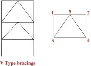
X type bracing system
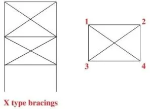
The X type bracing system is the most commonly used type for the deflection and drift controlling. In this type the bracings are connected to the each corner point of the bare frame in the X type shape. The complete bracing system model is shown in the below figure which is consisting of four corners namely 1, 2, 3 and 4. The bracings are connected in two diagonal directions through the points of 1 and 4, 2 and 3. With the help of the four joint connections at the each corner the building will be in stable condition structure will not move in X direction system and it will note move in Y direction system under the application of the lateral loading conditions like seismic loading condition and wind load condition and simultaneously it will not move in the deflection direction (height direction).
K type bracing system
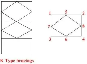
K type bracing systems are comes under the final type. In this case of bracing system the bracings ends are connected to the center point of the bare frame. The complete K type bracing model is shown in the below figure which is consisting of points 1, 2, 3, 4,5, 6, 7 and 8. The bracing model is connected with the 5, 8 and 6 in the right hand section of the bare frame and 5, 7 and 6 in the left hand section of the bare frame. Due to the presents of the center point of the bare frame connection for the bracing systems the additional stability increases in the building model as per the earth quake resistant building designs. With the help of the additional stiffness the value of the deflection in both X direction and Y direction in positive and negative directions decreases.
Similarly the value of the vertical deflection in the building structure decreases under the lateral loading condition system application like earth quake and wind load conditions as per the IS 1893 code standards in earth quake and IS 875 code for the wind load standards.
Conclusion:
Thus the drawing for the load path and identify the Axial force type in different type of bracing system below to resist horizontal shear & gravity load are drawn. Also, I stated that type of bracing system.