Week 1 Challenge
Question No: 1
Truss type reasoning
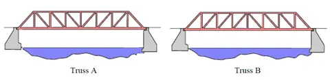
Out of the two through type truss systems shown below, which is the most efficient in carrying gravity load? Reason it out.
Aim:
To be find the most efficient to carrying the gravity load between the truss types A & B.
Observation:
As per your question, here I observed the types of the trusses are,
Truss A is Pratt Truss.
Truss B is Howe Truss.
Introduction:
Pratt Truss (Truss A):
The Pratt truss was first developed in 1844 under patent of Thomas and Caleb Pratt. Prevalent from the 1840s through the early twentieth century, the Pratt has diagonals in tension, verticals in compression, except for the hip verticals immediately adjacent to the inclined end posts of the bridge.
Howe Truss (Truss B):
A Howe truss is a truss bridge consisting of chords, verticals, and diagonals whose vertical members are in tension and whose diagonal members are in compression. The Howe truss was invented by William Howe in 1840, and was widely used as a bridge in the mid to late 1800s.
Procedure:
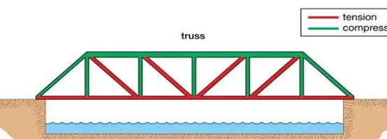
Fig: (1) Pratt Truss with Gravity Load.
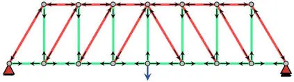
Fig: (2) Howe Truss with Gravity Load.
As per in the above figures, Pratt trusses have their vertical members in compression and diagonal members in tension upon the application of gravity loads at the joints of the top chord. For Howe trusses, the reverse becomes true as diagonal members are now in compression, while the vertical loads are in tension. As they are similar in structure to Pratt trusses, their uses are generally the same. To maximize the efficiency of the truss, the truss can be loaded at the joints of the bottom chord. Roof trusses can be loaded with a ceiling load for example.
Another thing to note is that, depending on the geometry and loading, Pratt trusses can have more unloaded members than Howe trusses.
Conclusion:
Pratt Truss (Truss A) reduces the cost of the structure due to more efficient members, reduces the self-weight, and eases the constructability of the structure. This type of truss is most appropriate for horizontal spans, where the force is predominantly in the vertical direction.
Result:
From that, Pratt Truss (Truss A) is the most efficient in carrying the gravity load than the Howe Truss (Truss B).
Question No: 2
Deflection shape & Bending Moment Drawing (Qualitative approach)
For the beam & Frame below draw deflected shape and bending moment drawing. (Qualitative approach). E & I are constants.
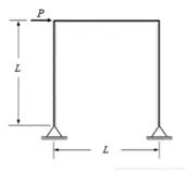
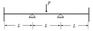
Fig: (a) Fig: (b)
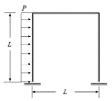
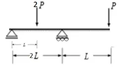
Fig: (c) Fig: (d)
Aim:
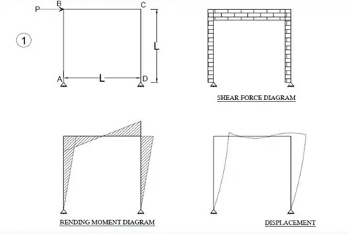
To show the deflection and bending moment drawing for the given beams and frames diagram.
Procedure:
Deflection and Bending Moment Diagram for Figure: (a)
Deflection and Bending Moment Diagram for Figure: (b)
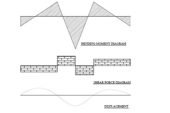
Deflection and Bending Moment Diagram for Figure: (c)
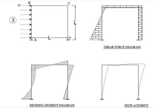
Deflection and Bending Moment Diagram for Figure: (d)
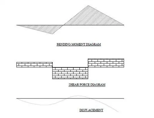
Result:
Thus, the deflection and bending moment diagram for the given beams and frames are shown in above diagram.
Question No: 3
Determine MOI, Weight, C/S area of sections below
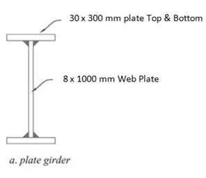
Aim:
To find the Moment of Inertia, Weight and Cross Section Area for above shown I - Section.
Given:
The given data are taken from the above shown I - Section diagram.
Procedure:
Step: 1
Calculate the Cross Section Area (A)
Area (A) = A1 + A2 + A3
A1 = b x h = 300 x 30 = 9000 mm2
A2 = b x h = 8 x 1000 = 8000 mm2
A3 = b x h = 30 x 300 = 9000 mm2
Total Area (A) = 9000 + 8000 + 9000 = 26000 mm2
Centre of co-ordinates for A1, A2, A3 are,
X1 = X2 = X3 = 0 mm.
Therefore X” = 0 mm.
Y1 = 1045 mm, Y2 = 530 mm, Y3 = 15 mm
Y” = (Y1 x A1) + (Y2 x A2) + (Y3 x A3)
A1 + A2 + A3
Y” = (1045 x 9000) + (530 x 8000) + (15 x 9000)
9000 + 8000 + 9000
Y” = 530 mm
Step: 2
Calculate Weight of the steel
Weight (W) = Density of steel (ρ steel) x Area
Density of steel (ρ steel) = 7860 Kg/m3
W = 7860 x (26000 x 10-6)
W = 204.36 Kg/m
Step: 3
Calculate Moment of Inertia
Izz = ((BH3)/12) – 2 x ((bh3)/12)
Izz = ((300 x (1060)3)/12) – 2 x ((146 x (1000)3/12)
Izz = 5.442 x 109 mm4
Iyy = 2 ((30 x 3003)/12) + ((1000 x 83)/12)
Iyy = 1.350 x 108 mm4.
Result:
- Total Area (A) = 26000 mm2
- W = 204.36 Kg/m
- Izz = 5.442 x 109 mm4
- Iyy = 1.350 x 108 mm4.

Aim:
To find the Moment of Inertia, Weight and Cross Section Area for above shown reinforced I - Section.
Given:
The given data are taken from the above shown reinforced I - Section diagram.
Procedure:
Step: 1
Calculate the Cross Section Area (A)
Area (A) = A1 + A2 + A3 + A4 + A5
A1 = b x h = 160 x 12 = 1920 mm2
A2 = b x h = 140 x 12.4 = 1736 mm2
A3 = b x h = 275.2 x 7.5 = 2064 mm2
A4 = b x h = 140 x 12.4 = 1736 mm2
A5 = b x h = 160 x 12 = 1920 mm2
Total Area (A) = 1920 + 1736 + 2064 + 1736 +1920 = 9376 mm2
Due to Symmetry
X” = 0 mm. and Y” = 162 mm
Step: 2
Calculate Weight of the steel
Weight (W) = Density of steel (ρ steel) x Area
Density of steel (ρ steel) = 7860 Kg/m3
W = 7860 x (9376 x 10-6)
W = 73.69 Kg/m
Step: 3
Calculate Moment of Inertia
Izz = 2 x ((160) x (12)3)/ 12) + (1920 x (156)2)
Izz = 9350 + (9821.6 x 104)
Izz = 1.917 x 108 mm4.
Iyy = (Moment of Inertia for ISMB 300) + 2 (12 x (160)3/ 12)
Iyy = (990.1 x 10⁴) + 8192
Iyy = 1.810 x 107 mm4.
Result:
- Total Area (A) = 9376 mm2
- W = 73.69 Kg/m
- Izz = 1.917 x 108 mm4.
- Iyy = 1.810 x 107 mm4.
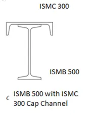
Aim:
To find the Moment of Inertia, Weight and Cross Section Area for above shown I – Section capped with C – Section or channel.
Given:
The given data are taken from the above shown I – Section capped with C – Section or channel diagram.
Step: 1
Calculate the Cross Section Area (A)
Area (A) = A1 + A2
A1 = Area of ISMC = 4563.71 mm2
A2 = Area of ISMB = 11074.38 mm2
Total Area (A) = 4563.71 + 11074.38 = 15638.10 mm2
Centre of co-ordinates for A1, A2, A3 are,
X1 = X2 = X3 = 0 mm.
Therefore X” = 0 mm.
Y1 = 484 mm, Y2 = 250 mm.
Y” = (Y1 x A1) + (Y2 x A2)
A1 + A2
Y” = (484 x 4536.71) + (250 x 11074.38)
4536.71 + 11074.38
Y” = 325.20 mm
Step: 2
Calculate Weight of the steel
Weight (W) = Density of steel (ρ steel) x Area
Density of steel (ρ steel) = 7860 Kg/m3
W = 7860 x (15368.10 x 10-6)
W = 123.00 Kg/m
Step: 3
Calculate Moment of Inertia
Izz = ((Moment of Inertia for ISMB) + A2d22) + ((Moment of Inertia for ISMC) + A1d12)
Izz = (45218.3 x 104 + (11074.38 x (250 – 325.20)2)) + (310.8 x 10⁴ + (4563.71 x ((500 +7.8 - 2.35) – 325.20)2)
Izz = 6.6620 x 108 mm4.
Result:
- Total Area (A) = 15638.10 mm2
- W = 123.00 Kg/m
- Izz = 6.6620 x 108 mm4.
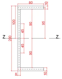
d. C -section Channel
Aim:
To find the Moment of Inertia, Weight and Cross Section Area for above shown C Section.
Given:
The given data are taken from the above shown C Section diagram.
Step: 1
Calculate the Cross Section Area (A)
Area (A) = A1 + A2 + A3
A1 = b x h = 80 x 10 = 800 mm2
A2 = b x h = 8 x 180 = 1440 mm2
A3 = b x h = 80 x 10 = 800 mm2
Total Area (A) = 800 + 1440 + 800 = 3040 mm2
Centre of co-ordinates for A1, A2, A3 are,
X1 = 40 mm, X2 = 4 mm, X3 = 40 mm.
Y1 = 195 mm, Y2 = 100 mm, Y3 = 5 mm.
Y” = (Y1 x A1) + (Y2 x A2) + (Y3 x A3)
A1 + A2 + A3
Y” = (195 x 800) + (100 x 1440) + (5 x 800)
800 + 1440 + 800
Y” = 100 mm
X” = (X1 x A1) + (X2 x A2) + (X3 x A3)
A1 + A2 + A3
X” = (40 x 800) + (4 x 1440) + (40 x 800)
800 + 1440 + 800
X” = 22.95 mm
Step: 2
Calculate Weight of the steel
Weight (W) = Density of steel (ρ steel) x Area
Density of steel (ρ steel) = 7860 Kg/m3
W = 7860 x (3040 x 10-6)
W = 23.89 Kg/m
Step: 3
Calculate Moment of Inertia
Izz = ((bh13)/12 + A1d12) + ((bh23)/12 + A2d22) + ((bh33)/12 + A3d32)
Izz = ((80 x 103)/12 + (800) x (95)2) + ((8 x 1003)/12 + (1440) x (0)2) + ((80 x 103)/12 + (800) x (95)2)
Izz = 1.834 x 107 mm4
Iyy = 2 ((10 x 803)/12) + (800 x 40 – (22.95 – 4)2) + ((180 x 83)/12) + (1440 x (22.95 – 4)2)
Iyy = 1.843 x 106 mm4.
Result:
- Total Area (A) = 3040 mm2
- W = 23.89 Kg/m
- Izz = 1.834 x 107 mm4.
- Iyy = 1.843 x 106 mm4.
Question No: 4
Load calculation problem
For the floor framing below, Calculate the load on interior beam, Exterior beam, Interior Girder and exterior girder having Floor Load of 10kN/m2
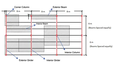
Aim:
To calculate the load on interior beam, Exterior beam, Interior Girder and exterior girder having Floor Load of 10kN/m2.
Given:
- Floor Load (FL) = 10 kN/m2.
- Distance to adjacent beam on right and left are taken from given diagram for interior beam, Exterior beam, Interior Girder and exterior girder.
Procedure:
Step: 1
Calculate the Tributary width (TW)
TW = 1/2 (Distance to Adjacent beam on right) + 1/2 (Distance to Adjacent beam on left)
TW = 1/2 x (Distance to Adjacent beam on right + Distance to Adjacent beam on left)
Tributary width of Interior Beam = 1/2 x (2+2) = 2 m
Tributary width of Exterior Beam = 1/2 x (0+2) = 1 m
Tributary width of Interior Grider = 1/2 x (8+8) = 8 m
Tributary width of Exterior Grider = 1/2 x (0+8) = 4 m
Step: 2
Calculate the Load on Beam and Grider
Load on Beam and Grider (L) = Tributary Width (TW) x Floor Load (FL)
Load on Interior Beam = 2 x 10 = 20 kN/m2
Load on Exterior Beam = 1 x 10 = 10 kN/m2
Load on Interior Grider = 8 x 10 = 80 kN/m2
Load on Exterior Grider = 4 x 10 = 40 kN/m2
Result:
- Load on Interior Beam = 20 kN/m2
- Load on Exterior Beam = 10 kN/m2
- Load on Interior Grider = 80 kN/m2
- Load on Exterior Grider = 40 kN/m2
Question No: 5
Expansion joint size determination for temperature stated problem
Assuming a bridge, made of steel, with an initial total length of 2000 m at -20 ºC, calculate the length difference at 40 ºC and its total length.
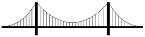
Coefficient of Thermal expansion of steel = 12x10-6/°C
Aim:
To Find the Length difference at 40 ºC and its total length.
Given:
- Initial Total Length (L0) = 2000m
- T1 = -20 ºC
- T2 = 40 ºC
- Coefficient of Thermal expansion of steel (α) = 12x10-6/°C
Procedure:
Step: 1
Calculate the Temperature Difference (ΔT)
ΔT = T2-T1
= 40-(-20)
ΔT = 60 ºC
Step: 2
Calculate the Length Difference (ΔL) at 40 ºC
ΔL = ((α) (L0) (ΔT))
ΔL = (12x10-6) x (2000) x (60)
ΔL = 1.44 m
Step: 3
Calculate its Total Length (L)
L = (L0) + ΔL
L = 2000 + 1.44
L = 2001.44 m
Result:
- Length Difference (ΔL) at 40 ºC = 1.44 m
- Total Length (L) = 2001.44 m