Week 2 Challenge
Design of Tension Member
Question: 1. Net Area for tension member calculation problem
Calculate the net section area for the tension member as shown in Figure below. The plate size is 260 x 20 thick and Bolt size is 20 mm.
Tip Steps:
- Refer Slide 26 for Net area calculation formula
- For angle section Flatten the member and calculate the gauge distance
Aim:
To be determine the net section area for the tension member as shown in figures below.
Plate – Drilled Hole
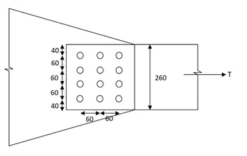
Given Data:
b = width of the plate = 260 mm
t = Thickness of the plate = 20 mm
dh = Diameter of bolt holes = Diameter of Bolts + 2 mm = 20 + 2 = 22 mm
n = Number of bolts = 4 nos.
Procedure:
Net Section Area (An) = (b – n dh) t
(An) = (260 – (4) x (22)) x 20
(An) = 3440 mm2
Result:
The Net Section area for the tension member (An) = 3440 mm2.
Plate – Zigzag bolting
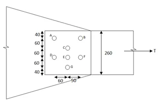
Given Data:
b = width of the plate = 260 mm
t = Thickness of the plate = 20 mm
dh = Diameter of bolt holes = Diameter of Bolts + 2 mm = 20 + 2 = 22 mm
Procedure:
For AD & BF
Net Area (An) = (b – n dh) t
Number of bolts (n) = 2 Nos.
(An) = (260 – 2 x 22) x 20
(An) = 4320 mm2.
For CEG
Net Area (An) = (b – n dh) t
Number of bolts (n) = 3 Nos.
(An) = (260 – 3 x 22) x 20
(An) = 3880 mm2.
For ACEG
(An) = (b – n dh + (P2 / 4g)) x t
Number of bolts (n) = 4 Nos.
(An) = (260 – 4 x 22 + (60)2/ (4 x 60)) x 20
(An) = 3740 mm2.
For BCEG
(An) = (b – n dh + (P2 / 4g)) x t
Number of bolts (n) = 4 Nos.
(An) = (260 – 4 x 22 + (50)2/ (4 x 60)) x 20
(An) = 3648 mm2.
For ACF and BCD
(An) = (b – ∑dh + ∑ (P2 / 4g)) x t
Number of bolts (n) = 3 Nos.
(An) = (260 – 3 x 22 + (60)2/ (4 x 60)) + ((50)2 / (4 x 60)) x 20
(An) = 4388 mm2.
For BCF and ACD
Number of bolts (n) = 3 Nos.
(An) = (260 - 3 x 22 + 2(502)/ (4 x 50) x 20
(An) = 4380 mm2
Result:
The BCEG having minimum value of Net Section area (An) = 3648 mm2 with 4 nos. of bolts
So Net Section Area for Zig Zag bolting (An) = 3648 mm2
Angle (200 x 100 x 12 with M20 bolt)
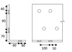
Given Data:
(l x h) = 200 x 100 mm, b = 200 + 100 = 300 mm
Thickness (t) = 12 mm
Diameter of the holes (dh) = Diameter of the bolt + 2 mm = 20 + 2 = 22 mm.
Procedure:
Net Section Area (An) = (b – n dh + ∑ (P2 / 4g)) x t
(An) = (300 – 3 (22) + (50)2/ 4 x (90) + (50)2/ 4 x (130)) x 12
(An) = 2949.02 mm2.
Result:
The Net Section area for the angle (An) = 2949.02 mm2.
Question: 2. Sag rod design problem
Design a sag rod as shown in Figure below. Purlins are supported at 1/3rd points by sag rods.
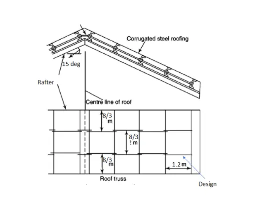
Assume center to center distance of Rafter spaced at 8 m, spacing of purlin = 1.2 m, Self-weight of roofing (including thermal insulation) = 60 kg/m2, Wind pressure intensity = 150 kg/m2, Slope of rafter = 15 degrees, Live Load =75 kg/m2. Assume self-weight of purlin as 100 kg/m.
Tip Steps:
- Calculate total gravity load (DL & LL) on the purlin
- Calculate Wind load acting on the purlin. Note that wind load acts perpendicular to the member.
- Resolve and calculate the load acting parallel to the roof
- Force contribution to each sag rod is calculated
- Calculate required net area and chose a desired sag rod size.
Aim:
To be determine the load on sag rod and purlin.
Given Data:
Rafter space = 8m
Purlin spacing = 1.2m
Self-weight of roofing (including thermal insulation) = 60 kg/m2
Wind pressure intensity = 150 kg/m2
Slope of rafter = 15 degrees
Live Load =75 kg/m2
Assumed self-weight of purlin = 100 kg/m.
Procedure:
Total Gravity Load (Tg) = m x g x h
= (60 + 75) x 9.8 x 1.2 x 8
(Tg) = 12700 N
Load on a Sag rod or Threaded rod
Tdn = (Tg/ 3 + w x g x s/3) Sin Ө
= (12700/3 + 100 x 9.8 x (8/3)) x Sin (15 ̊)
Tdn = 1772 N
Desired size of Sag rod.
Tdn = 0.9 x An x Fu / 1.25
Fu = 250 MPa
1772 = 0.9 x An x Fu / 1.25
An = (1772 x 1.2) / (0.9 x 250)
(An) = 9.844 mm2.
D = (4 x An / Π) 0.5
D = (4 x 9.844 / Π) 0.5
D = 3.54 mm
Force Contribution to each sag rod
F = (5/8) x w x Sin Ө x s x 4
F = (5/8) x 100 x 9.81 x Sin 15 ̊ x 8 x 4
F = 5062.00 N
Net Area required
An = F/ 0.6 x fy
An = 5062 / (0.6 x 250)
An = 6.5 mm2.
Result:
- Total gravity load (Tg) = 12700 N
- Load on sag rod or threaded rod (Tdn) = 1772 N
- Size of the sag rod (D) = 3.54 mm
- Force contribution to sag rod (F) = 5062.00 N
- Required Net Area (An) = 6.5 mm2.
Question: 3. Determine section size for given tensile load
Design a single angle member of length 5m to carry axial tensile force of 500 kN. Yield strength fy of the material to be considered is 350 N/mm2.
Tip Steps :
- Calculate required area of cross section from factored load
- Choose an angle section from required area calculated
- Calculate design strength of the member due to yielding
- Calculate design strength of member by tearing of net section
- For a given member assume bolts placed with appropriate edge/end/pitch/gauge distance and calculate block shear capacity
- Check slenderness is within limit
Aim:
To be determine the calculations to design the strength of member.
Given Data:
Single angle member of length = 5m
Axial tensile force = 500 kN
Yield strength Fy = 350 N/mm2.
Procedure:
Here to be consider the data as follows
Weld size (t) = 4 m,
Fy = 250 MPa,
Fu = 410 MPa
Approximate gross area = 1.1 x Tdg/fy = 1.1 x 250 x 1000/250 = 1100 mm2
From steel table, select ISA 100 x75 x 8mm connected to gusset plate by longer length Cxx
Area of connected leg = (100 - 8/2) x 8 = 768mm2
Area of outstanding leg = (75 - 8/2) x 8 = 568mm2
Ag = 768+568 = 1336mm2 > 1100mm2
Therefore it’s Safe.
Design strength due to yielding of gross section
Tdg = Ag Fy/ rmo
Tdg = (0.91 x 1336 x 250)/ 11000
Tdg = 304.00 KN
Design strength due to rupture at net section
Tdn = α x An x Fu /rml
Fu = 0.8 x 1336 x 410/1000
Fu = 438.21 KN
Design strength due to block shear
For calculation of block shear, length of weld is required
P1 x 100 = 250 x (100 -31) = 172.50KN
P2 = 250 - 172.50 = 77.5 KN
Strength of 4mm weld
= 0.7 x 4 x 0.462 x 410
S = 530.37 KN/mm
Effective length of weld on head side (EL1)
(EL1) = (172.5 x 1000) /530.37
(EL1) = 325 mm
Effective length of weld on toe side (EL2)
(EL2) = (77.5 x 1000) /530.37
(EL2) = 146 mm
Total welded length (L) = (EL1) + (EL2)
(L) = 325 + 146
(L) = 471 mm
Avg = Avn = 471 x 8 = 3768 mm2
Atg = Atn = 100 x 8 = 800mm2
Tdb1 = 0.525 Avg x Fy + 0.72 x Atn x Fy
Tdb1 = 0.525 x 3768 x 250/1000 + 0.72 x 800 x 410/1000
Tdb1 = 730.31 KN
Tdb2 = 0.416 Avn x Fu + 0.91 x Atg x Fy
Tdb2 = (0.416 x 3768 x 410) /1000 + (0.91 x 800 x 250) /1000
Tdb2 = 824.67 KN
Result:
Tensile strength provided = 438.21 KN, 304.00 KN and 730.71 KN
All Provided strengths are > 250KN
Therefore the Design of the angle member is in safe condition.
Conclusion:
Here for all 3 questions are solved or designed for the given tension members as per their data and tips in the questions.