Week-6 Calculate the Stretch Ratio by comparing the ELFORM (-2,-1,1,2) with Ogden_Material Model.
AIM: To simulate tensile behavior for the model with of 10mmx10mmx10mm dimension with 10 elements for each direction and use the material card attached (Ogden_Material.k) and plot graphs.
PROCEDURE:
- Firsr we will open .k file in LS-DYNA.
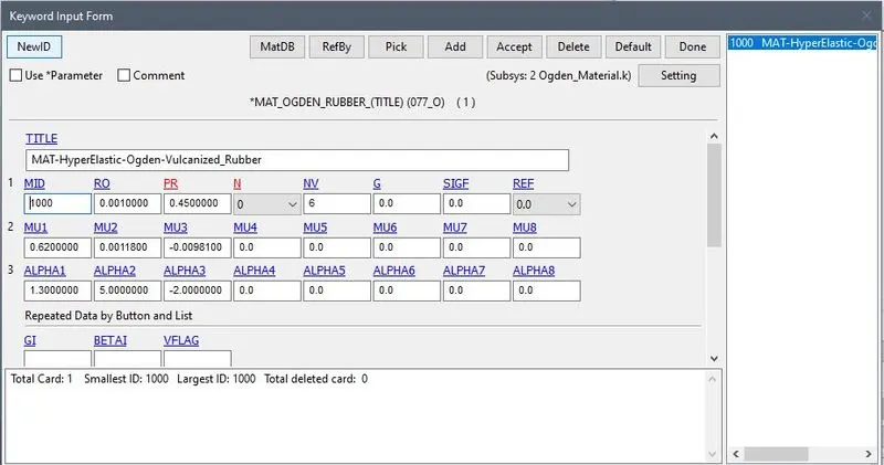
- Now we have to apply card to the model so for that we have to create the box model.
- To create box model go to the MESH>SHAPEMESHER and then give the dimesion of the box.
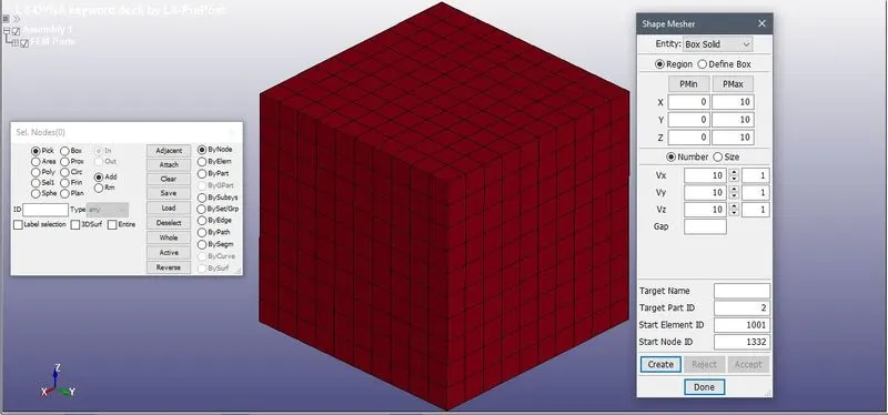
- Now we hav to select section for it with different ELFORM= 1, 2, -1, -2.
- For that go to MODEL>KEYWRD>SECTION>SOLID
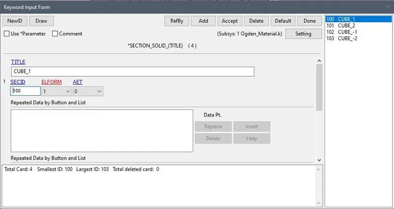
NOTE: We will use different types of ELFORM to check the variations in results.
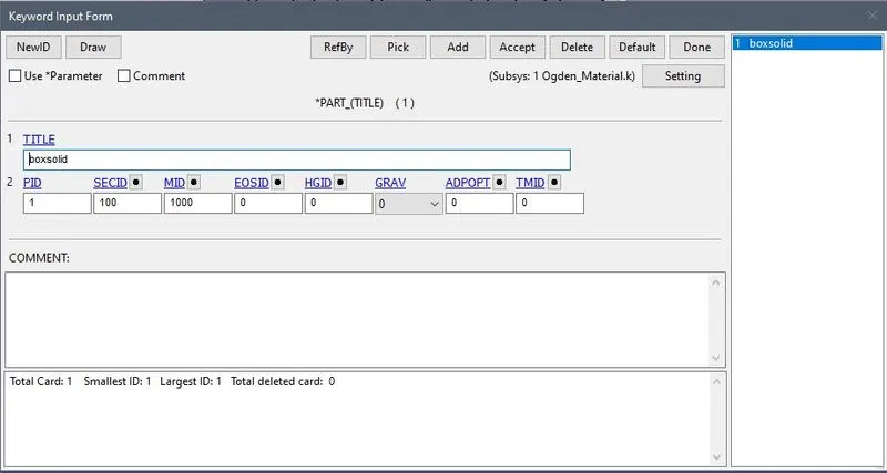
- Now we will apply the material and section to the PART we created.
- For that go to MODEL>KEYWRD>PART
- Now for the boundary conditions to the box model.
- Here we constrained the one side of the box. And then give the prescribed motion to the opposite side.
- Because we have to simulate the tensile stress.
For this go to MODEL>CREENT>BOUNDARY>SPC
- First we will constrained all nodes in X direction.
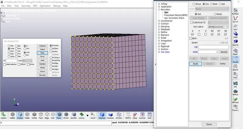
- Now next we will constrained vertical in Z direction.
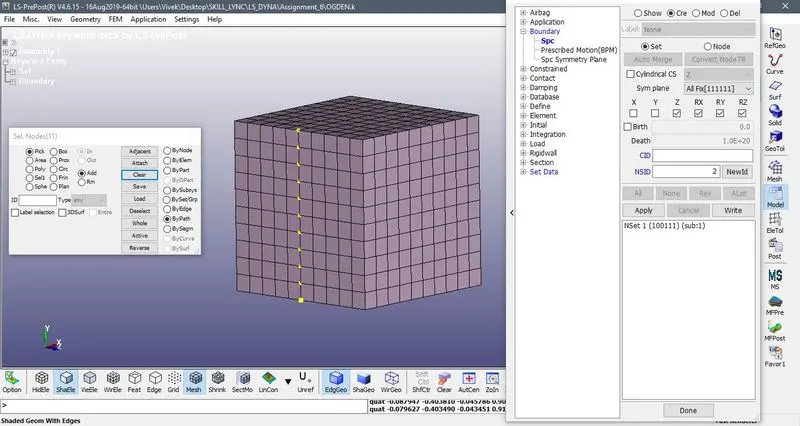
- Horizontal Constrained in Y direction
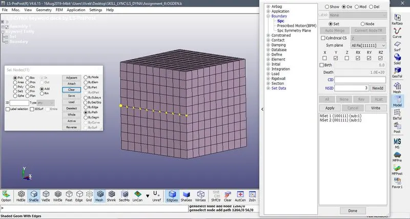 .
.
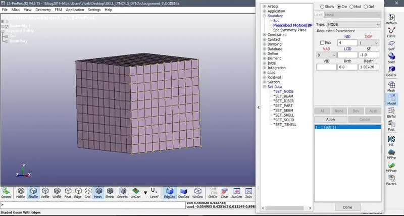
- Now the next is prescribed motion.
- So we will give the motion to the Opposite face of the
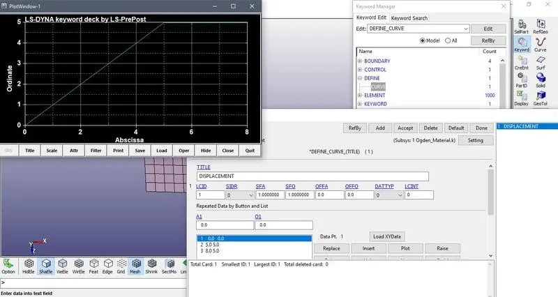
- The prescribed motion has to be defined to give a displacement by assigning a curve. The box is subjected to tension at X- direction and the plot figured up to stretch ratio 5 in all cases.
- We can to create a curve for this.
- For that go to MODEL>KEYWRD>DEFINE>CURVE
- Now we have applied BCS we have to apply control card for the simulation.
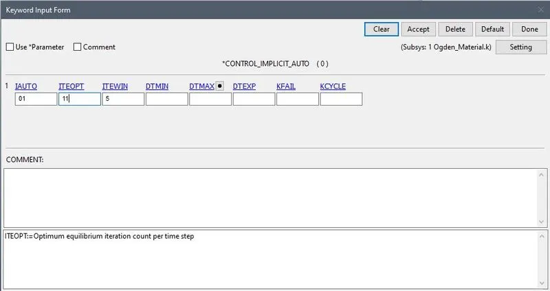
- For that go to the MODEL>CONTROL>IMPLICIT_AUTO
- It is used to defined the timstep for the IMPLICIT simulation.
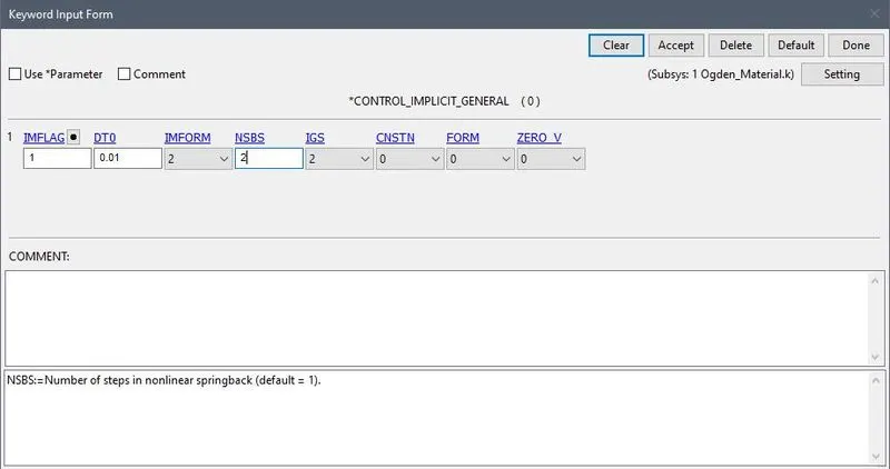
- Now next MODEL>CONTROL>IMPLICIT_GENERAL
- This Control card activate the implicit function.
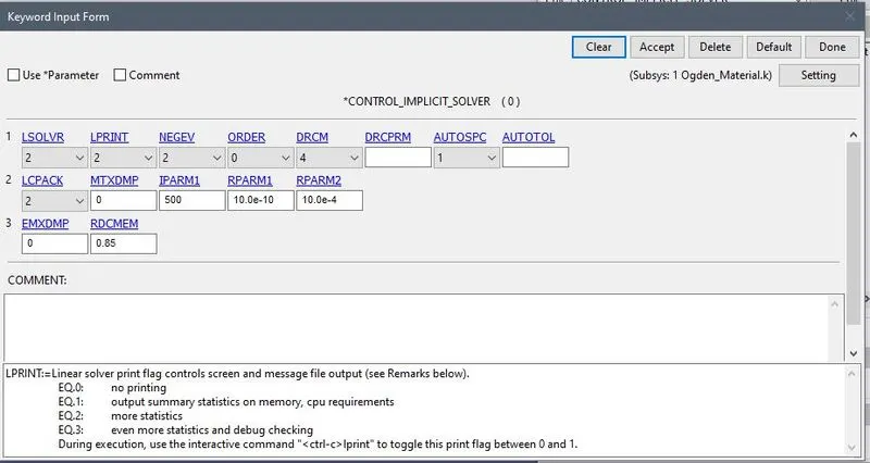
- Next is MODEL>CONTROL>IMPLICIT_SOLVER
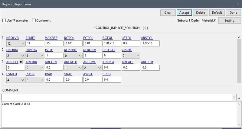
- Now MODEL>CONTROL>IMPLICIT_SOLUTION
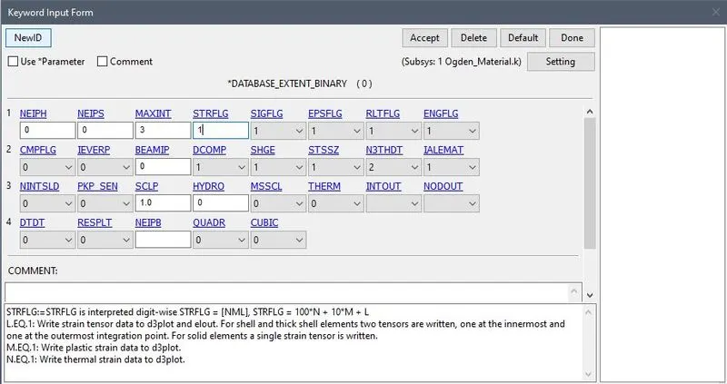
- Now next is for the OUTPUT that we required for that first MODEL>KEYWRD>DATABASE>EXTENT_BINARY
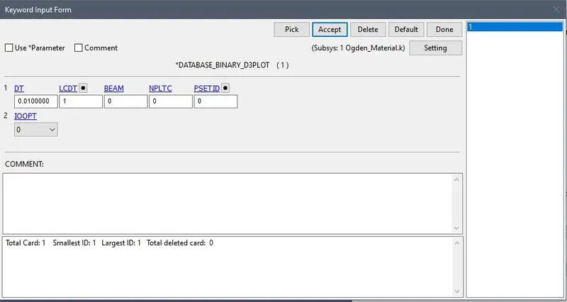
- MODEL>KEYWRD>DATABASE>BINARY_D3PLOT
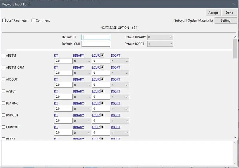
- MODEL>KEYWRD>DATABASE>ASCII_option
- We will select GLSTAT, MATSUM, NODOUT for the output with DT=0.01
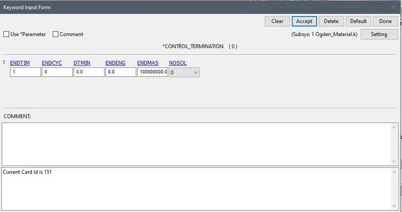
- For data termination go to the MODEL>KEYWRD>CONTROL>TERMINATION
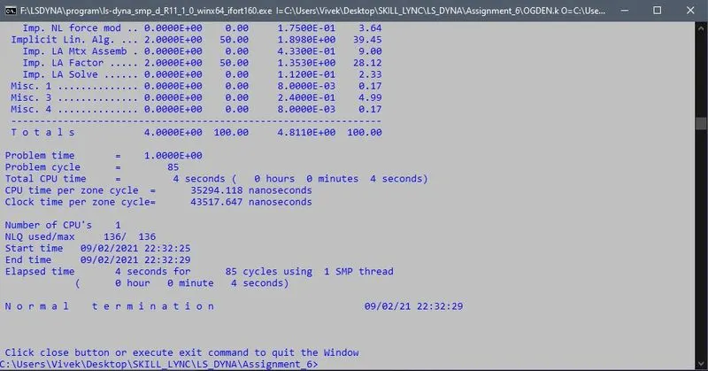
- Now we will run the .k file.
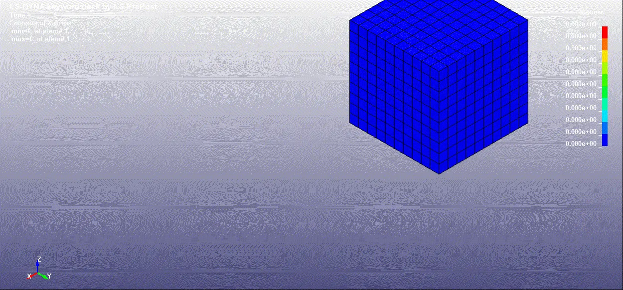
D3PLOT:
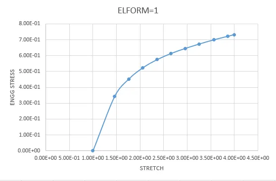
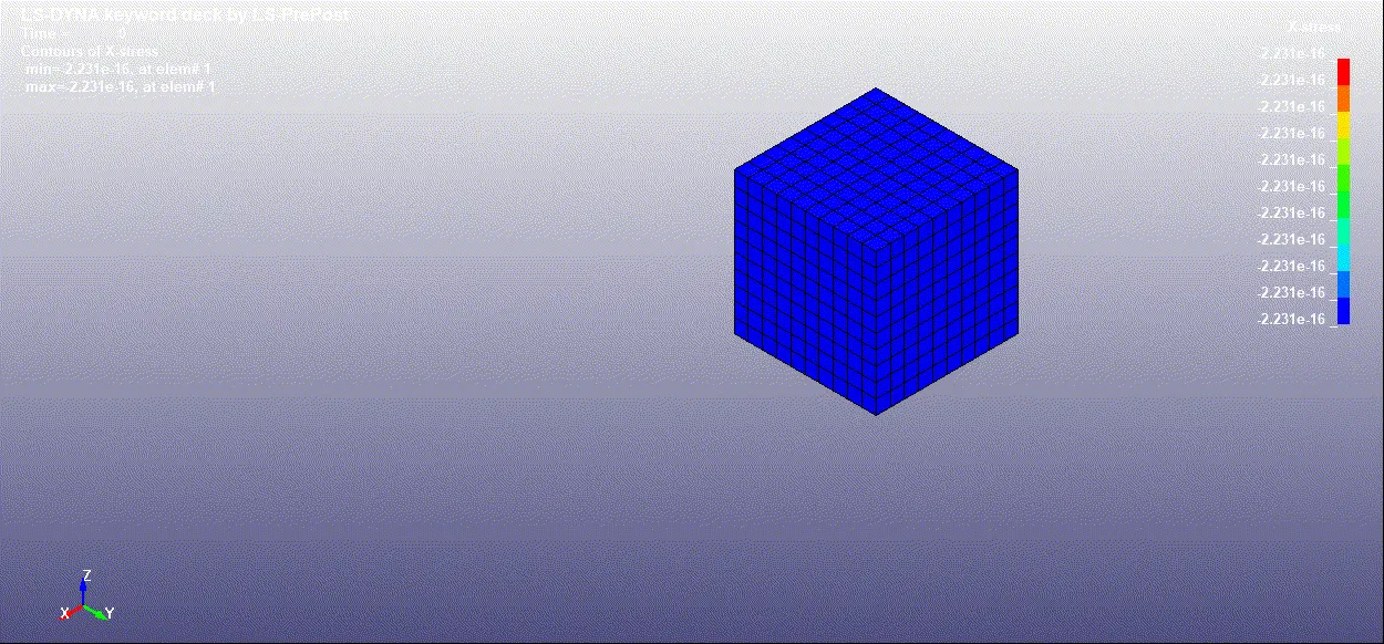
ELFORM=1
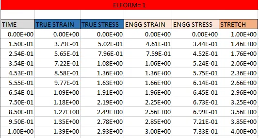
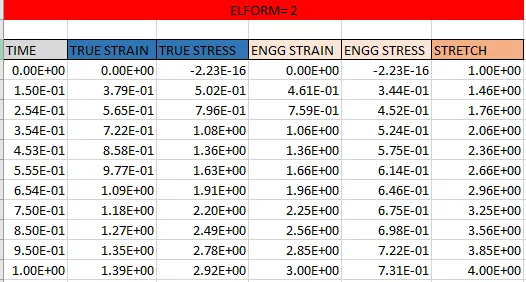
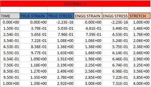
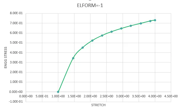
- Now with the help of FringComp we will get the data of true stress and strain and with the help of that we will plot Engineering stress Vs Stretch Ratio
- The formulae given below:
Ɛtrue = ln ( 1 + Ɛeng)
Ɛeng = EXP Ɛtrue – 1
σ true = σeng (1+ Ɛeng )
Ɛtrue = true strain
Ɛeng = Engineering Strain
σ true = True stress
σeng = Engineering stress
ELFORM=2

ELFORM=-1
ELFORM=-2
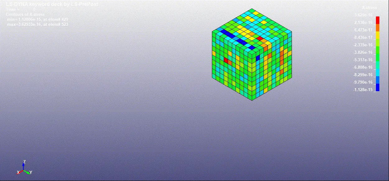
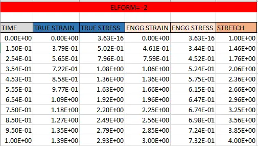
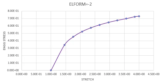
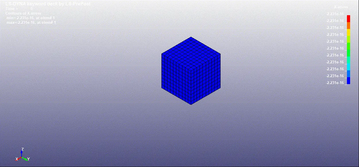
- FE model of solid block was created with ogden material to simulate uniaxial tension test for different cases of ELFORM (1, -1, 2, -2).
- The Engineering stress/strain and stretch ratio was calculated to plot a graph of Engg. stress vs stretch ratio up to stretch ratio 4.
- The uniaxial tension test was solved using implicit solver since the analysis is similar to a quasi-static analysis on a hyperelastic non-linear material with slow steady loading conditions.