Week-6 Calculate the Stretch Ratio by comparing the ELFORM (-2,-1,1,2) with Ogden_Material Model.
AIM:
To perform the simulation using ELFORM =1,-1,2,-2 and calculate the stretch ratio.
OBJECTIVE:
- Create a block of 10mmx10mmx10mm dimension with 10 elements for each direction and use the material card attached (Ogden_Material.k) that is representative of the material properties from the above figure.
- Use appropriate boundary conditions to simulate tensile behavior for the model and finally compare the results from your simulation to the plot above up to stretch ratio 5. Only the uniaxial plot is to be compared.
- Compare the results for the simulation using ELFORM = 1, 2, -1, -2
- Use a proper solver (Implicit/Explicit) and also explain the reason.
PROCEDURE:
STEP 1:
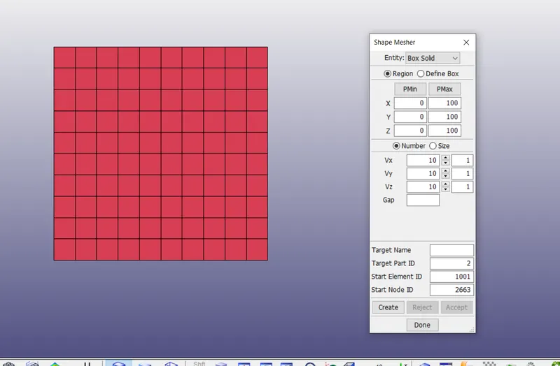
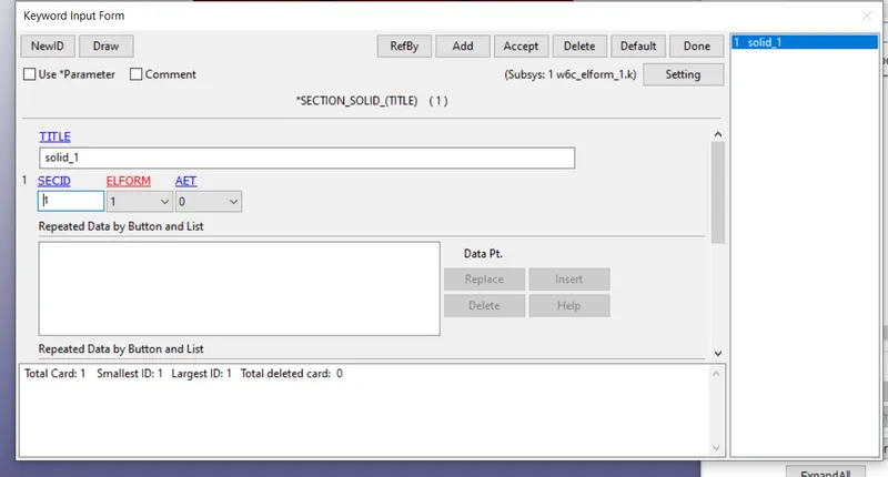
The FE model of a asolid block of 10mm*10*10mmdimension with 10 element for each direction is created using the mesh tab as shown in the image
STEP 2:
BOUNDARY-SPC:
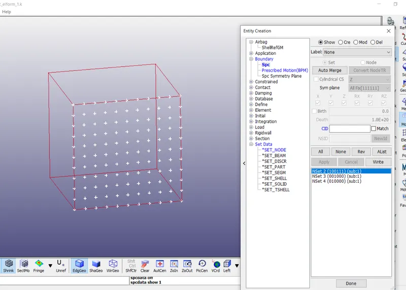
The nodes in the moving facesa are selected for applying load.
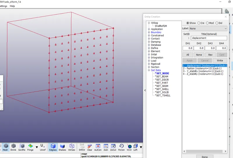
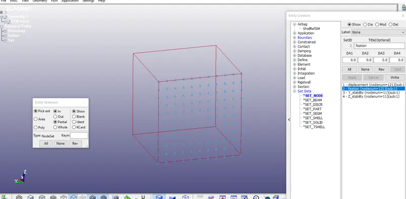
To perform the uniaxial tensile test on the specimen ,the nodesa of one of the faces are fixed along the X-axis.
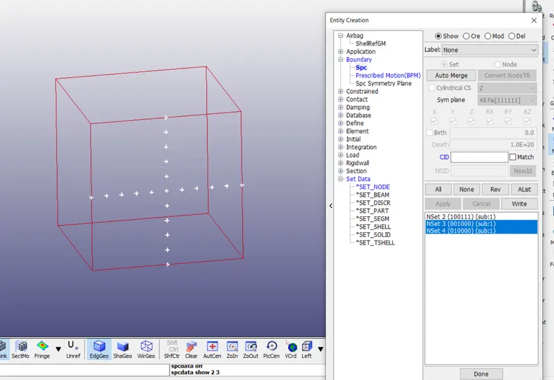
Then we fix the vertical middle nodes along Z-direction fixed in Y-direction.
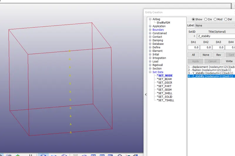
Then we fix the horizontal middle nodes along Y-direction fixed in Z-direction.
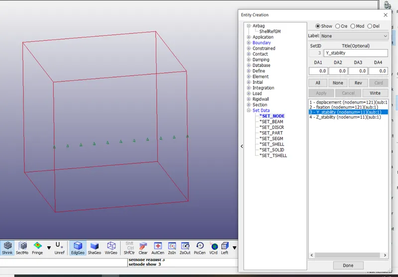
The SPC-SET wfor dispalcement and fixation.
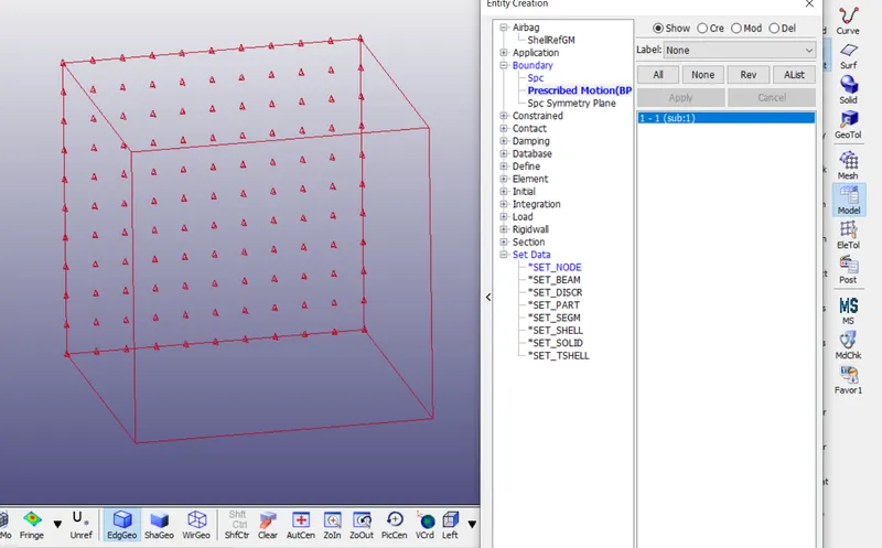
The prescribed motion set to the selected nodes move along the X-axis.
STEP 3:
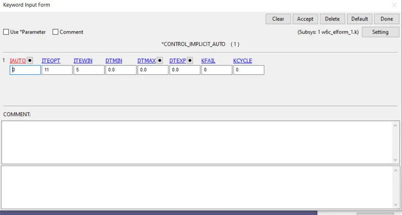
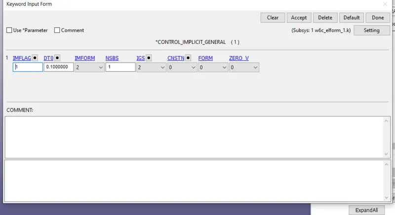
Control_implicit card has been created.
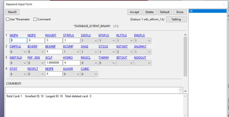
DATABASE_EXTENT_BINARY card with STRFLG=1 AS SHOWN IN figure is used to compute the elastic strain in the model.
STEP 4:
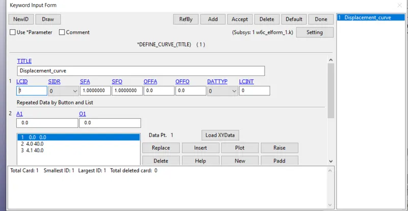
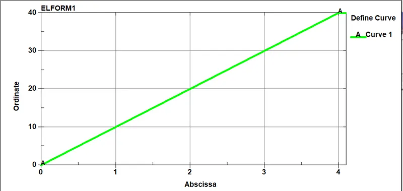
DEFINE_CURVE
The minimum load to be applied on the morning surface to attain a stretch ratio of 5,
True strain=ln(1+engg.strain)
stretch ratio=1+engg strain
5=1+(deltaL/L)
Delta L= 40mm
Hence, the minimum value of 40mm is taken to define the load curve
STEP 5:
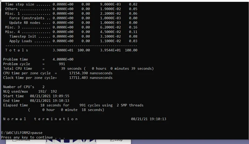
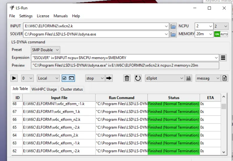
Run the simulation.
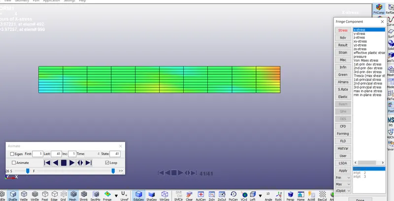
The final simulation of ELFORM 1------XSTRESS
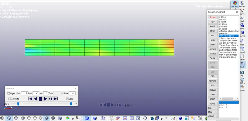
VON-MISES STRESS
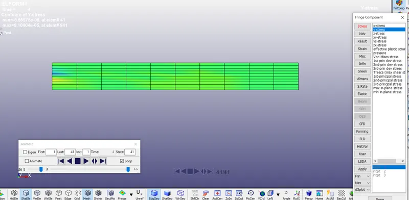
Y-STRESS
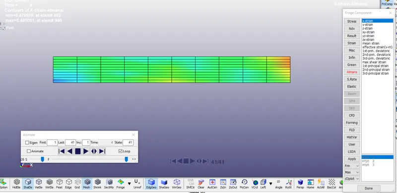
ALMANS----X-STRAIN
THE FINAL SIMULATION OF ELFORM 1
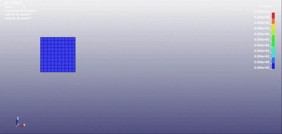
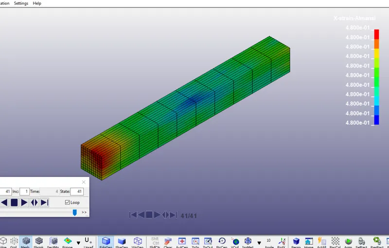
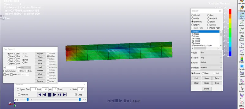
PLOTTING OF X-STRESS
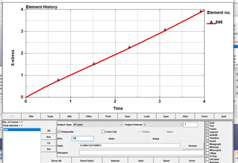
PLOTTING OF LOWER IPT X-STRAIN
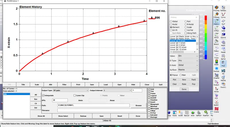
Put up in the notepad++
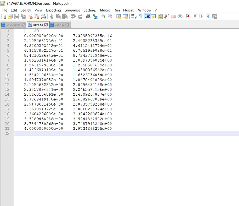
STEP 6:
Engineering stress is the applied load divided by the original cross-sectional area of a material. Also known as nominal stress.
True stress is the applied load divided by the actual cross-sectional area (the changing area with respect to time) of the specimen at that load
Engineering strain is the amount that a material deforms per unit length in a tensile test. Also known as nominal strain.
True strain equals the natural log of the quotient of current length over the original length.
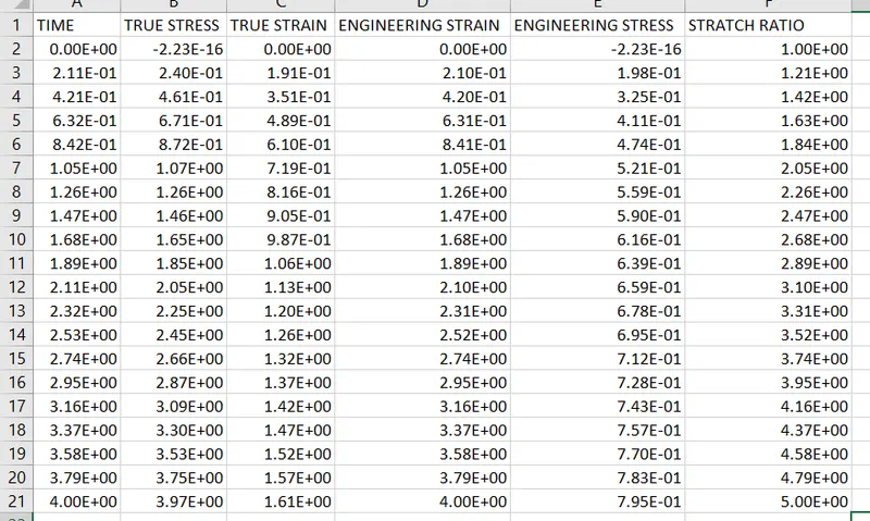
TRUE STRESS σt= σe(1+εe)
ENGG STRESS, σe=σt/(1+εe)
TRUE STRAIN,εt= ln(1+εe)
ENGG STRAIN, εe=EXPεt-1
STRETCH RATIO λ=1+ εe
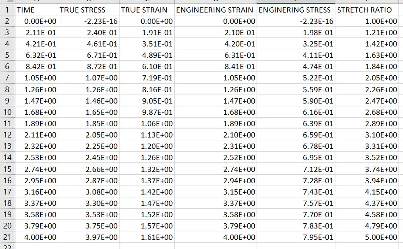
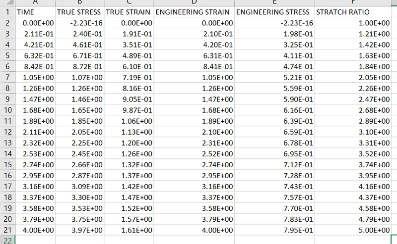
Calculate the ELFORM IN the xcel sheet.
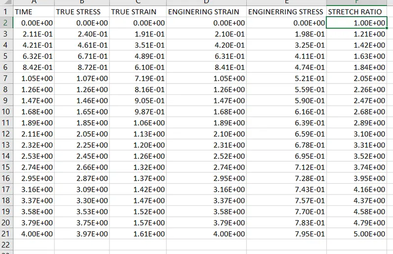
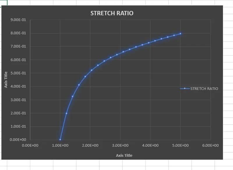
STEP 7:
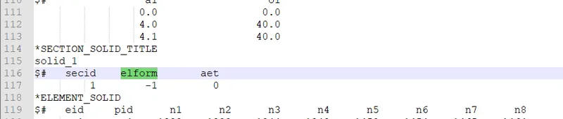
ELFORM -1
Change the ELFORM in the notepad++ .Then run the simulation.
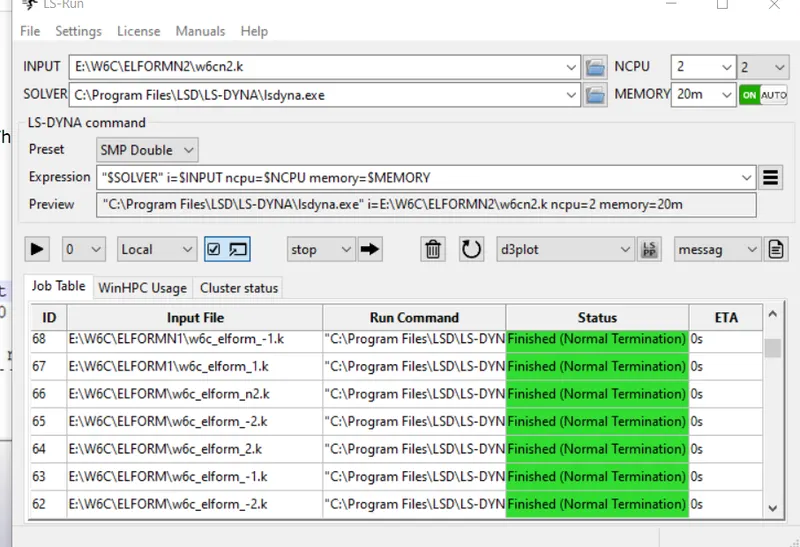
The final simulation of ELFORM -1
The excel plot for ELFORM -1
STEP 8:
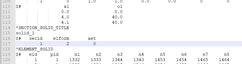
ELFORM 2
Change in th notepad++ then run the simulation.
The final simulation of ELFORM 2
STEP 9:
ELFORM -2
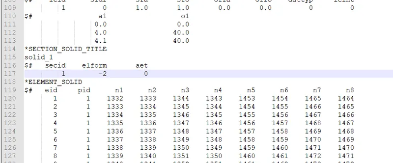
Change the ELFORM IN NOTEPAD++ then run the simulation.
The final simulation of ELFORM -2
CONCLUSION:
The result between enginnering stress and stretch ratio is plotted for different formulation there is no significant changes except the computational time, the tensile test of cube is very small stimulation the difference might be noted in big problem eith small aspect ratio.from the simulation ELFORM1 has low computational time followed by ELFORM 2,where ELFORM-2 has more computational time than ELFORM-1.
An implicit method was used to solve this tension problem as the rate of displacement imposed on the model was very low and thus,it was similar to a quasi-static analysis on a hyperelastic non-linear material.