Week-6 Calculate the Stretch Ratio by comparing the ELFORM (-2,-1,1,2) with Ogden_Material Model.
*AIM:-
Calculate the Stretch Ratio by comparing the ELFORM (-2,-1,1,2) with Ogden_Material Model.
*Objective:-
-Create a block of 10mmx10mmx10mm dimension with 10 elements for each direction and use the material card attached (Ogden_Material.k) that is representative of the material properties from the above figure.
-Use appropriate boundary conditions to simulate tensile behavior for the model and finally compare the results from your simulation to the plot above up to stretch ratio 5. Only the uniaxial plot is to be compared.
-Compare the results for the simulation using ELFORM = 1, 2, -1, -2
-The unit of µ in the material definition is in MPa and α is a dimensionless quantity. Modify those quantities according to your unit systems.
-Use a proper solver (Implicit/Explicit) and also explain the reason.
*Procedure:-
1 create the FEA model
2 Define section solid card
3 Assigning material & section to their respective parts
4 Creating boundary conditions
5 Providing the displacement
6 Setting up the control cards for implicit analysis
7 Binary_D3plot & ASCII_opction define
8 Model check
9 post-processing
1) create the FEA model:-
-First of all open the ogden_material.k file in LSPP.
-Now next step is create the FEA model.
-For that first of all create the cube which has 10mmx10mmx10mm dimension.
-shall mesh on every surfaces using 1 mm size.
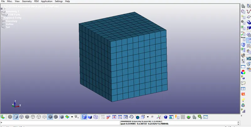
2) Define section solid card:-
-After the creation of FEA model, next step is create the section_solid card.
-Here, provide element formulation is 1.
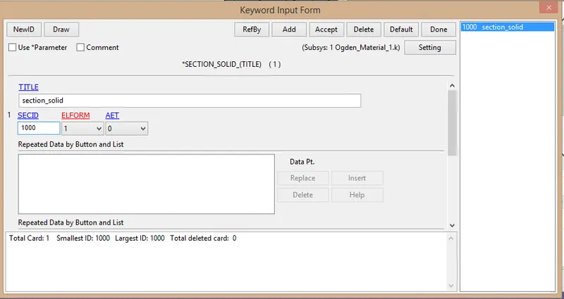
3) Assigning material & section to their respective parts:-
-After the creation of material & session , next step is create the part.
-Here there is two parts available. provide the material id and section id for them.
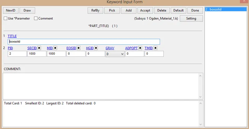
4) Creating boundary conditions:-
-In this simulation we use to one face nodes are fixed & nodes of opposite face provide to motion.(Tensile stress)
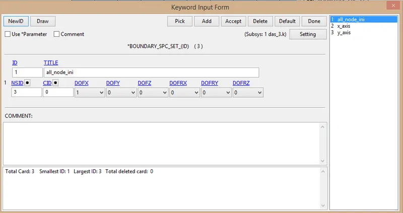
*SPC_SET:-
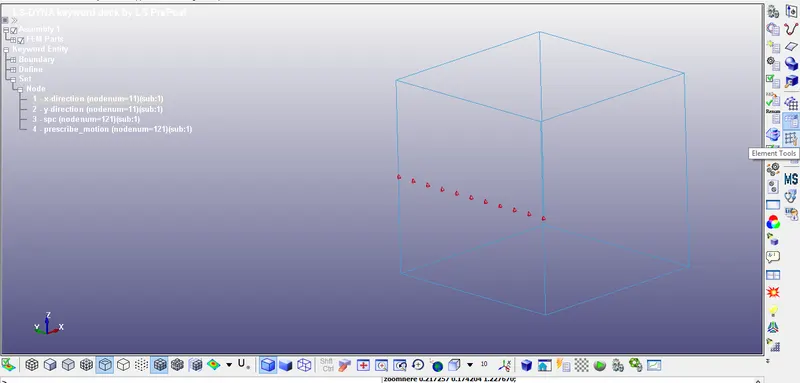
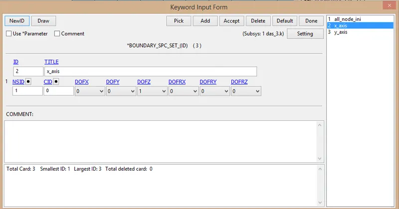
-Here, we constrain in only z-direction.
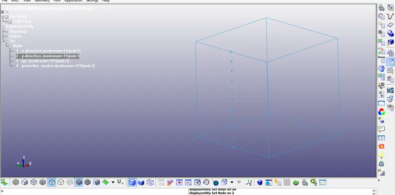
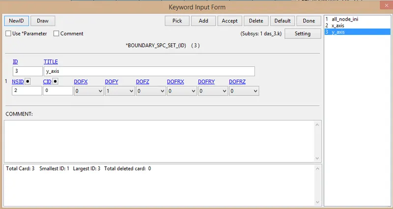
-Here, we constrain in only y-direction.
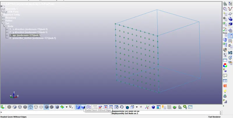
-Here, we constrain in only x-direction.
5) Providing the displacement:-
*Boundary_Prescribe_motion:-
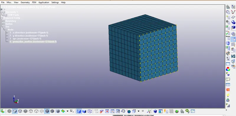
-First of all create new node set.
-For that go to model & part>create> Set data> set node
-Here, select one surface is selected.
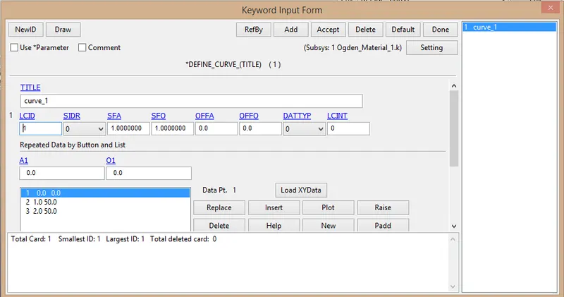
-Here, another thing is LCID define.
-The minimum load applied on the moving surface to attain stress ratio is 5, is calcuated using following relation,
stress ratio:-
`λ=1+ε_e`
But, `ε_e=(δl)/l`
`λ=1+(δl)/l`
`5=1+(δl)/10`
`δl=10×4`
`δl=40 mm`
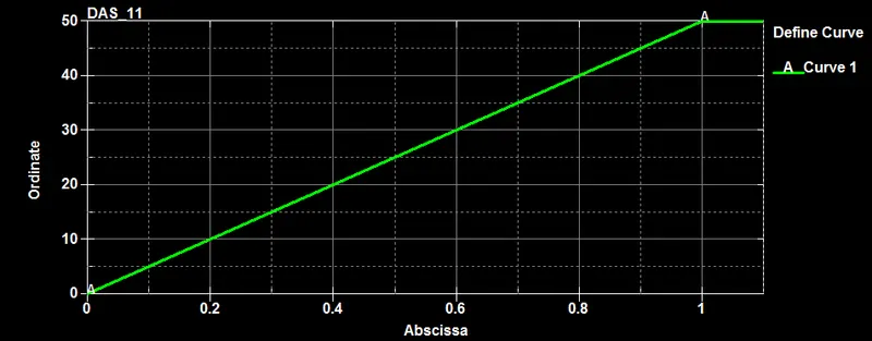
-Hence, minimum value of 50 mm is taken to define the load curve.
-For that Go to Model & part> keywords manager> all> Define> curve
-plot of the curve:-
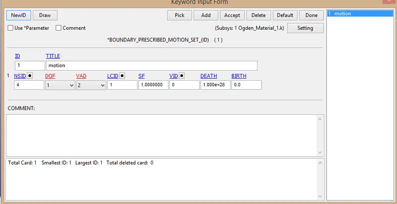
-After that go to Model & part> keywords manager> all> Boundary> prescribe_motion_set
-Here, provide various value is:-
DOF=1 (Due to provide displacement in only x-direction
VAD=2(For the acceleration)
SF=1 (because we require same value provide in the curve)
6) Setting up the control cards for implicit analysis:-
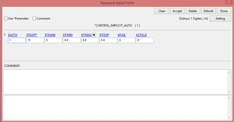
*CONTROL_IMPLICIT_AUTO:-
-It is used for automatic timestep control during implicit analysis.
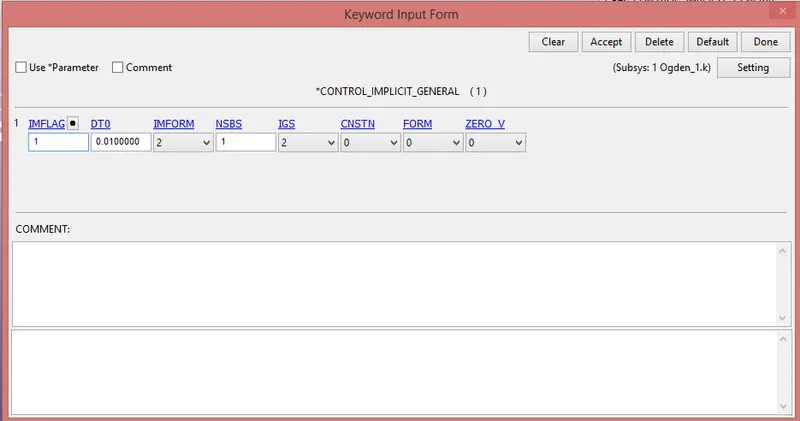
*CONTROL_IMPLICIT_GENERAL:-
-It is used to activate implicit analysis & define associated control parameters.
-This keyword is used for all implicit analysis simulation.
-Input value:-
IMFLAG=1
DTo=0.01
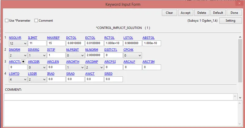
*CONTROL_IMPLICIT_SOLUTION:-
-It is used for specify linear or non-linear solution.
-Here, we use to default value.
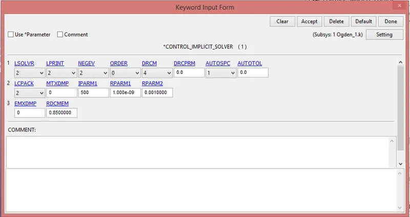
*CONTROL_IMPLICIT_SOLVER:-
-It is used for implicit calculation.
-Here, we use to default value.
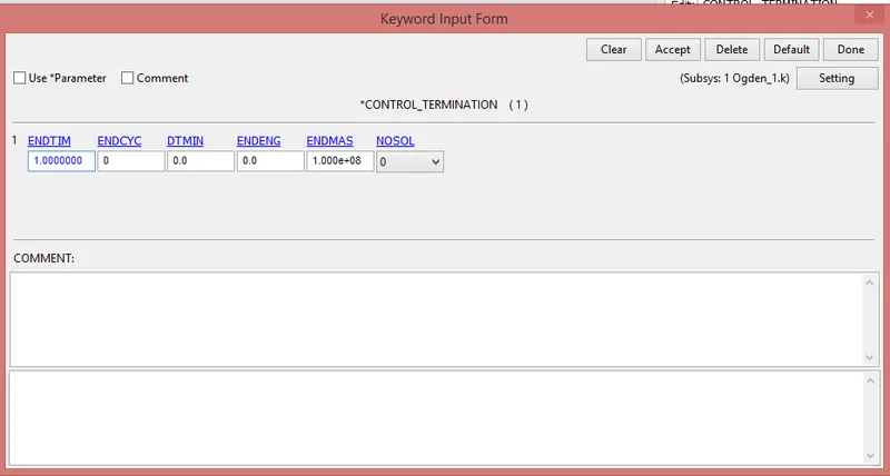
*Control termination card:-
-This card is useful for the provide end time to simulation.
-Here, the end time is 1 ms.
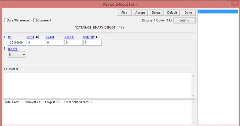
7) Binary_D3plot & ASCII_opction define:-
*BINARY_D3PLOT:-
In this keyword the frequency with which the animation is to be crated will be given and is set to 0.01 ms.
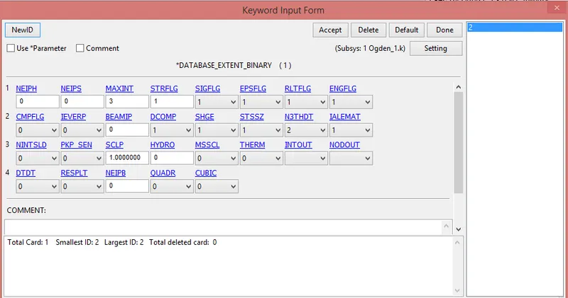
*EXTENT_BINARY:-
8) Model check:-
-After assigning all the keyword check the model using the model checker and make sure that the file is error file.
-After that save the file as a".k" format.
-Run the file in the solver. if it's end as a normal termination then model is correct.
9) Post processing:-
-The D3 file open in LSPP using opction File>open>LS-DYNA binary plot
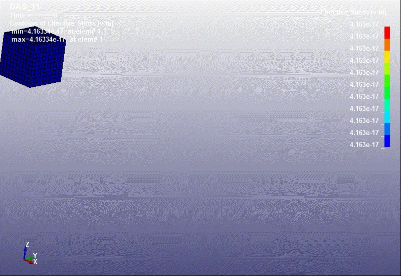
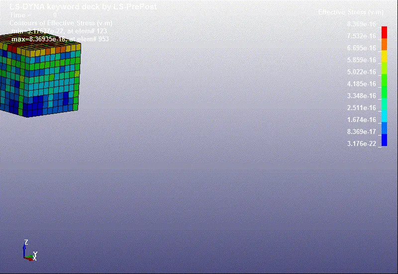
1)Animation of von-mises stress is as shown below:-
*ELFORM=1 *ELFORM=2
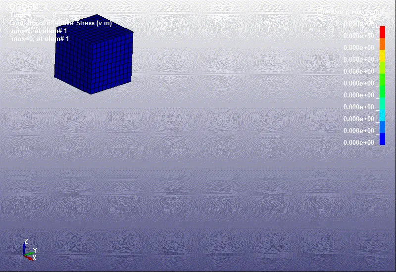
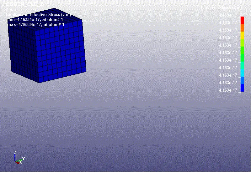
*ELFORM=-1 *ELFORM=-2
2) The animation of effective strain contour:-
*ELFORM=1 *ELFORM=2
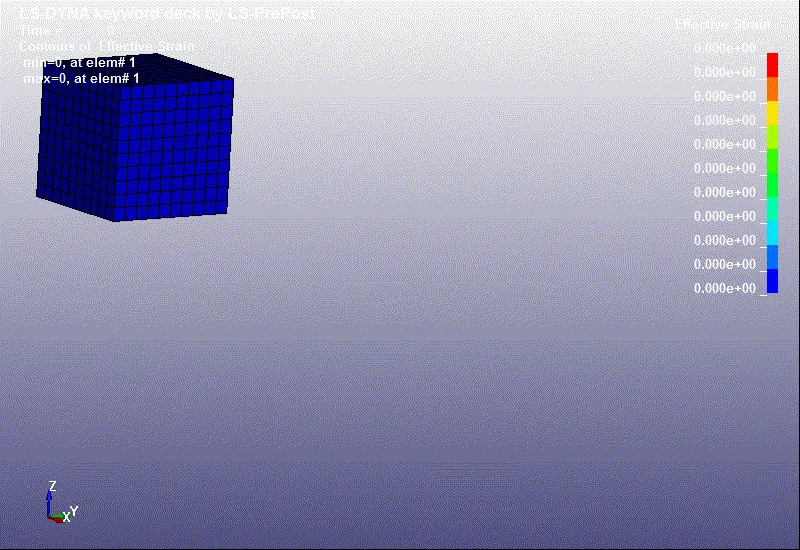
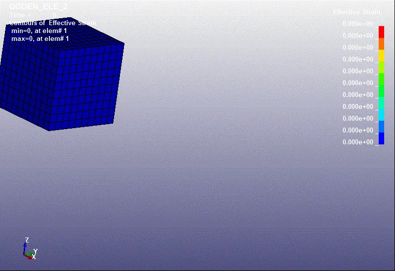
*ELFORM=-1 *ELFORM=-2
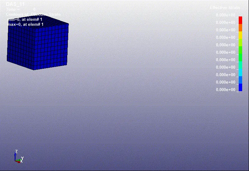
3)Calculation of engineering stress, strain & stretch ratio:-
-In the LS-DYNA software the output of stress and strain from post fringe component is true stress & true strain.
-For find engineering stress & engineering strain below equations are used.
-We know that , `ε_T=ln(1+ε_e)`
then,Engineering strain `ε_e=e^((ε_T))-1` (eq..1)
Stretch ratio , `λ=1+ε_e` (eq..2)
`σ_T=σ_e (1+ε_e)`
`σ_T=σ_e×λ`
`σ_e=σ_T/λ` (eq..3)
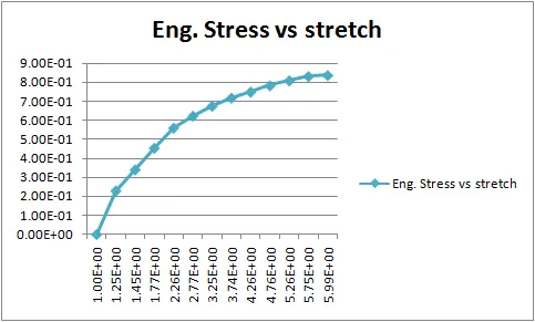
*Find engineering stress, strain & stretch ratio for ELFORM=1:-
| ELFORM_1 | |||||
| TRUE | ENGINEERING | ||||
| time | x-stress | x-strain | x-stress | x-strain | lemda |
| 0 | 1.51E-15 | 0 | 1.51E-15 | 0 | 1.00E+00 |
| 0.051 | 0.288 | 0.227 | 2.30E-01 | 0.25483 | 1.25E+00 |
| 0.0908 | 0.495 | 0.374 | 3.41E-01 | 0.453537 | 1.45E+00 |
| 0.154 | 0.804 | 0.57 | 4.55E-01 | 0.768267 | 1.77E+00 |
| 0.254 | 1.27 | 0.817 | 5.61E-01 | 1.263699 | 2.26E+00 |
| 0.354 | 1.73 | 1.02 | 6.24E-01 | 1.773195 | 2.77E+00 |
| 0.454 | 2.2 | 1.18 | 6.76E-01 | 2.254374 | 3.25E+00 |
| 0.554 | 2.69 | 1.32 | 7.19E-01 | 2.743421 | 3.74E+00 |
| 0.654 | 3.2 | 1.45 | 7.51E-01 | 3.263115 | 4.26E+00 |
| 0.754 | 3.73 | 1.56 | 7.84E-01 | 3.758821 | 4.76E+00 |
| 0.854 | 4.26 | 1.66 | 8.10E-01 | 4.259311 | 5.26E+00 |
| 0.954 | 4.79 | 1.75 | 8.32E-01 | 4.754603 | 5.75E+00 |
| 1 | 5.02 | 1.79 | 8.38E-01 | 4.989452 | 5.99E+00 |
*plot for ELFORM=1:-
*Find engineering stress, strain & stretch ratio for ELFORM=2:-
| ELFORM_2 | |||||
| TRUE | ENGINEERING | ||||
| time | x-stress | x-strain | x-stress | x-strain | lemda |
| 0 | 1.51E-15 | 0 | 1.51E-15 | 0 | 1.00E+00 |
| 0.051 | 0.288 | 0.227 | 2.30E-01 | 0.25483 | 1.25E+00 |
| 0.0908 | 0.495 | 0.374 | 3.41E-01 | 0.453537 | 1.45E+00 |
| 0.154 | 0.804 | 0.57 | 4.55E-01 | 0.768267 | 1.77E+00 |
| 0.254 | 1.27 | 0.817 | 5.61E-01 | 1.263699 | 2.26E+00 |
| 0.354 | 1.73 | 1.02 | 6.24E-01 | 1.773195 | 2.77E+00 |
| 0.454 | 2.2 | 1.18 | 6.76E-01 | 2.254374 | 3.25E+00 |
| 0.554 | 2.69 | 1.32 | 7.19E-01 | 2.743421 | 3.74E+00 |
| 0.654 | 3.2 | 1.45 | 7.51E-01 | 3.263115 | 4.26E+00 |
| 0.754 | 3.73 | 1.56 | 7.84E-01 | 3.758821 | 4.76E+00 |
| 0.854 | 4.26 | 1.66 | 8.10E-01 | 4.259311 | 5.26E+00 |
| 0.954 | 4.79 | 1.75 | 8.32E-01 | 4.754603 | 5.75E+00 |
| 1 | 5.02 | 1.79 | 8.38E-01 | 4.989452 | 5.99E+00 |
*plot for ELFORM=2:-
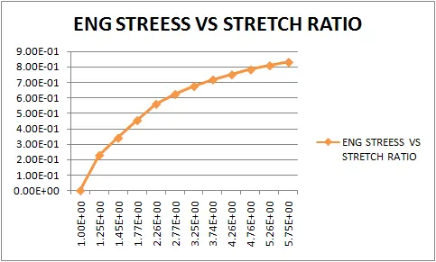
*Find engineering stress, strain & stretch ratio for ELFORM=-1:-
| ELFORM_-1 | |||||
| TRUE | ENGINEERING | ||||
| time | x-stress | x-strain | x-stress | x-strain | lemda |
| 0 | 1.51E-15 | 0 | 1.51E-15 | 0 | 1.00E+00 |
| 0.051 | 0.288 | 0.227 | 2.30E-01 | 0.25483 | 1.25E+00 |
| 0.0908 | 0.495 | 0.374 | 3.41E-01 | 0.453537 | 1.45E+00 |
| 0.154 | 0.804 | 0.57 | 4.55E-01 | 0.768267 | 1.77E+00 |
| 0.254 | 1.27 | 0.817 | 5.61E-01 | 1.263699 | 2.26E+00 |
| 0.354 | 1.73 | 1.02 | 6.24E-01 | 1.773195 | 2.77E+00 |
| 0.454 | 2.2 | 1.18 | 6.76E-01 | 2.254374 | 3.25E+00 |
| 0.554 | 2.69 | 1.32 | 7.19E-01 | 2.743421 | 3.74E+00 |
| 0.654 | 3.2 | 1.45 | 7.51E-01 | 3.263115 | 4.26E+00 |
| 0.754 | 3.73 | 1.56 | 7.84E-01 | 3.758821 | 4.76E+00 |
| 0.854 | 4.26 | 1.66 | 8.10E-01 | 4.259311 | 5.26E+00 |
| 0.954 | 4.79 | 1.75 | 8.32E-01 | 4.754603 | 5.75E+00 |
| 1 | 5.02 | 1.79 | 8.38E-01 | 4.989452 | 5.99E+00 |
*plot for ELFORM=-1:-
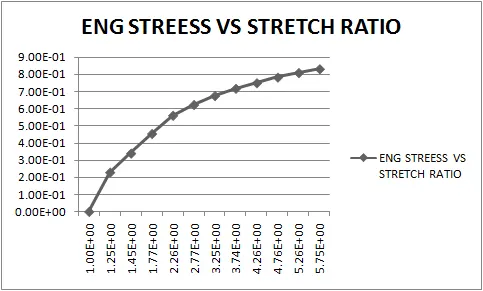
*Find engineering stress, strain & stretch ratio for ELFORM=-2:-
| ELFORM_-2 | |||||
| TRUE | ENGINEERING | ||||
| time | x-stress | x-strain | x-stress | x-strain | lemda |
| 0 | 1.51E-15 | 0 | 1.51E-15 | 0 | 1.00E+00 |
| 0.051 | 0.288 | 0.227 | 2.30E-01 | 0.25483 | 1.25E+00 |
| 0.0908 | 0.495 | 0.374 | 3.41E-01 | 0.453537 | 1.45E+00 |
| 0.154 | 0.804 | 0.57 | 4.55E-01 | 0.768267 | 1.77E+00 |
| 0.254 | 1.27 | 0.817 | 5.61E-01 | 1.263699 | 2.26E+00 |
| 0.354 | 1.73 | 1.02 | 6.24E-01 | 1.773195 | 2.77E+00 |
| 0.454 | 2.2 | 1.18 | 6.76E-01 | 2.254374 | 3.25E+00 |
| 0.554 | 2.69 | 1.32 | 7.19E-01 | 2.743421 | 3.74E+00 |
| 0.654 | 3.2 | 1.45 | 7.51E-01 | 3.263115 | 4.26E+00 |
| 0.754 | 3.73 | 1.56 | 7.84E-01 | 3.758821 | 4.76E+00 |
| 0.854 | 4.26 | 1.66 | 8.10E-01 | 4.259311 | 5.26E+00 |
| 0.954 | 4.79 | 1.75 | 8.32E-01 | 4.754603 | 5.75E+00 |
| 1 | 5.02 | 1.79 | 8.38E-01 | 4.989452 | 5.99E+00 |
*plot for ELFORM=-2:-
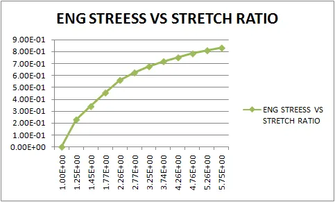
-From this data, we concude that there are no change of engineering stress, strain & stretch ratio even change of ELFORM. Then loading condition of this model is simple.