Tetra or 3D meshing on the housing, crank housing and chassis assembly
*aim:-
-mesh the various model using tetra or 3D mesh as per given quality criteria.
*medel:1:-
*google drive link of model:-
https://drive.google.com/file/d/1cFukr7dX_elamW_4C6HWJXorfK8qQo1n/view?usp=sharing
*Model name:-
Hosing
*Methodology:-
1)Import the model
2) Geometry cleanup
3) Creation of 2D tria meshing as per quality criteria
4) Convert 2D tria to 3D tetra
5) Check 3D quality of mesh
*what is a idea behind tetra meshing:-
-here, simply we first of all create trai mesh on all surfaces and check the quality of meshing, after that we convert 2D tria to 3D tetra and then check the quality of 3D meshing.
*which time we use tetra or 3D meshing?
-if thickness of of the surfaces in the model is more then 5 mm then that time we use tetra meshing or 3D meshing.
-if the thickness of surfaces in the model is less than 5 mm then we use 2d meshing(mid surfacing and meshing). we provide the thickness after the meshing..
1)Import the model:-
-The format of the file is STP, then first of all select import solver deck command, choose import geometry type and select file type is STEP.
-Now select the file from our folder and import it.
-But it is not visible on our screen due to graphical issue , for that use f key and then its visible.
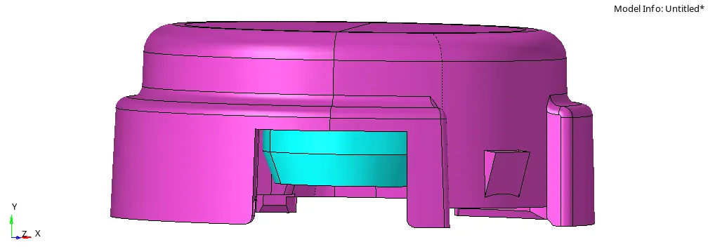
-but here we not seen perfectly lines on surfaces. for that we convert auto mode to topo mode.
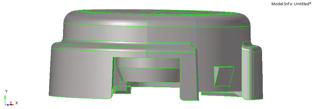
-here, there are two components are available.
1)Hub ; 2) cover
2) Geometry cleanup:-
-After import a model, we focuss on geometry.
-it is required for achieve better result of mesh flow.
-if distance between two adjustance surfaces is lessthen the value of minimum size given by the designer, then its always fail for minimum size, due to that geometry cleanup are main part of any preprocessing software.
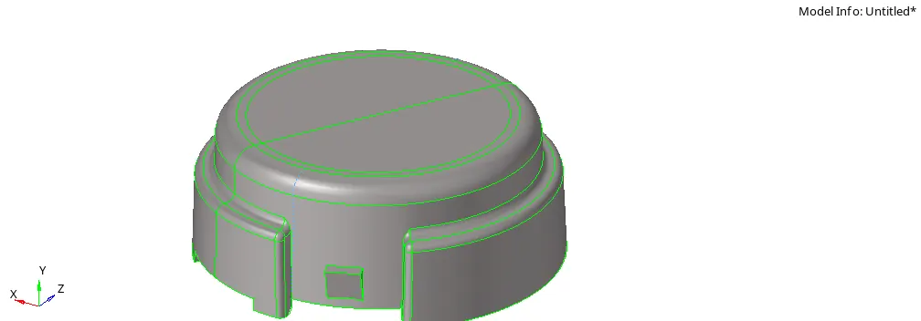
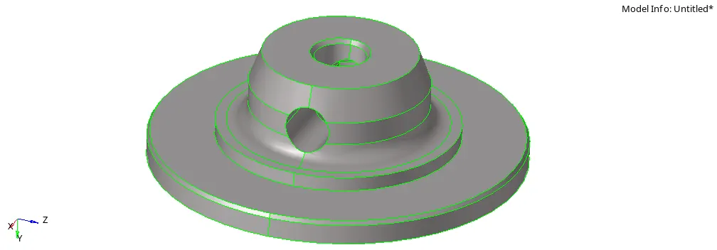
-all components after geometry cleanup:-
*cover:-
*Hub:-
3) Creation of 2D tria meshing as per quality criteria:-
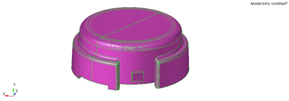
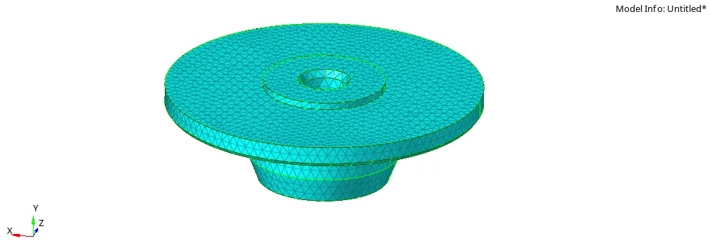
-after complete of geometry cleanup, we create 2D tria mesh on the all surfaces.
-for that use following quality criteria.
Elements sizes:- Minimum length -2 mm,
Target length - 5mm,
Maximum length - 7mm
-for that choose automesh command and select all surfaces using surface via display.
-here, main point is type of mesh is only tria.
-after that remesh elements by elements for best result of meshing.
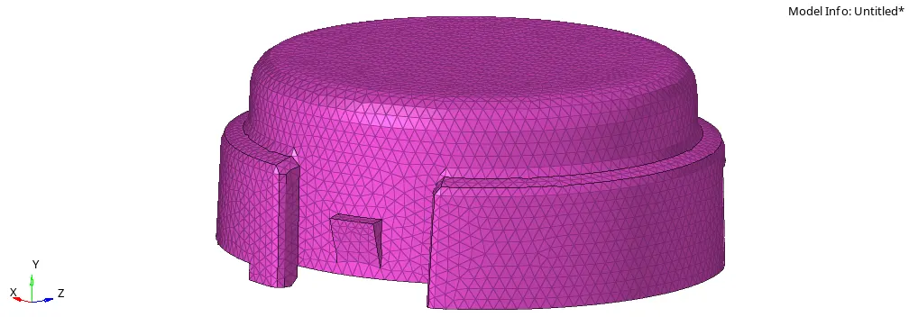
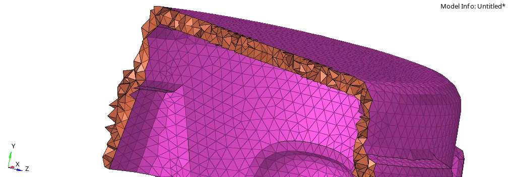
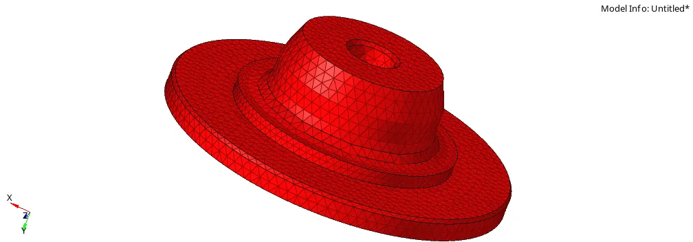
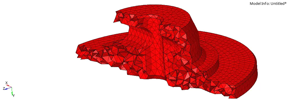
4) Convert 2D tria to 3D tetra:-
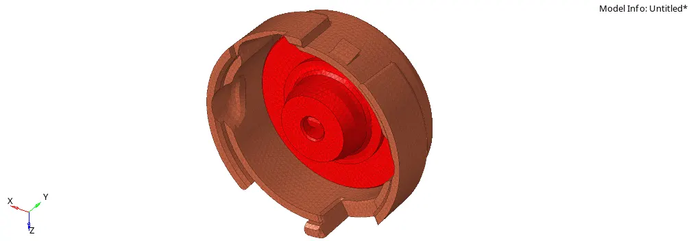
-now next step is we convert 2D tria elements to 3D tetra elements.
-for that use tetra mesh command, and select the overall elements using display opction and create a mesh.(3D>tetra mesh>tetra mesh)

5) Check 3D quality of mesh:-
-After the conversion of 2D to 3D tetra elements, we check the quality of mesh.
-the main important quality for 3D tetra meshing is tet-collapse.
-here value required of tet collapse is more than 0.15
-we remove tet collapse elemets by elements using translate command.(Tool>translate)
*model:2:-
*google drive link of model:-
https://drive.google.com/file/d/12juCyI6AQuB0hB1g7jEtFAQObqGaGWgn/view?usp=sharing
*Model name:-
crank housing
*Methodology:-
1)Import the model
2) Geometry cleanup
3) Creation of 3D meshing
4) Check 3D quality of mesh
the model:-
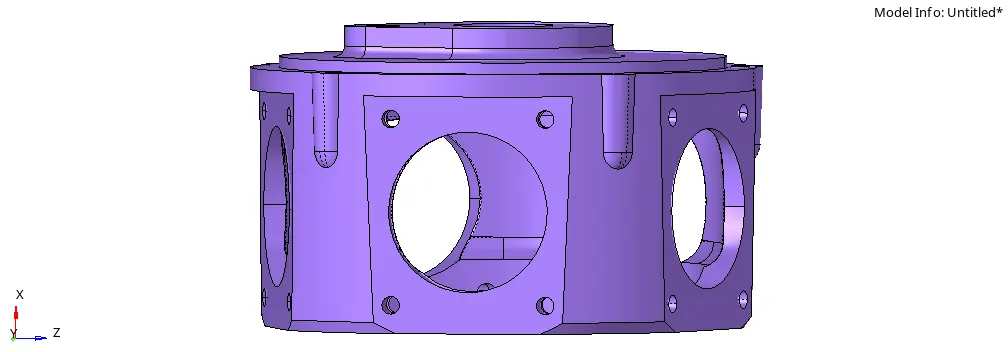
-The format of the file is hm , then first of all select import solver deck command, choose import model type.
-after that select the file from our folder and import it.
-But it is not visible on our screen due to graphical issue , for that use f key and then its visible.
2) Geometry cleanup:-
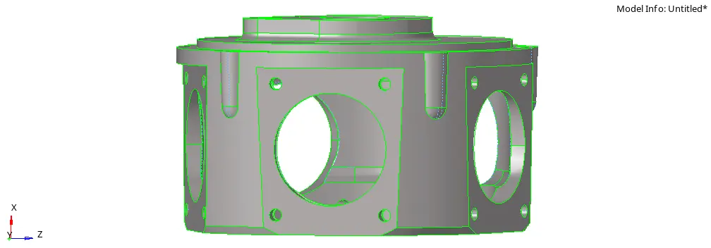
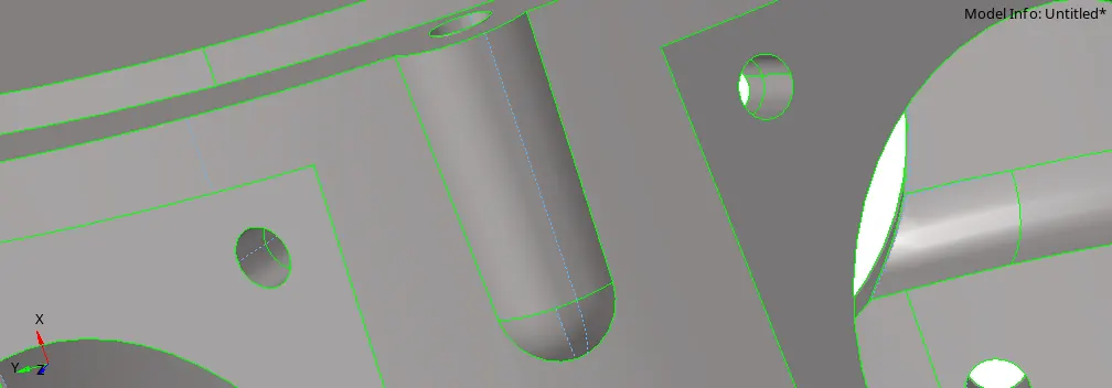
-After import a model, we focuss on geometry.
-it is required for achieve better result of mesh flow.
-if distance between two adjustance surfaces is lessthen the value of minimum size given by the designer, then its always fail for minimum size, due to that geometry cleanup are main part of any preprocessing software.
3) Creation of 3D meshing:-
-now next step is create 3D meshing in the component.
-for that use tetra mesh command and choose components and create a mesh.

-here we select create per-volume comps opction for create a new tetra component.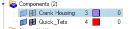
4) Check 3D quality of mesh:-
-After the create 3D mesh, we check the quality of mesh.
-the main important quality for 3D tetra meshing is tet-collapse.
-here value required of tet collapse is more than 0.15
-we remove tet collapse elemets by elements which are failled using translate command.(Tool>translate)
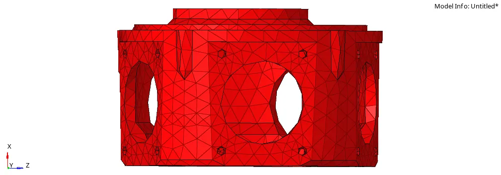
*model:3:-
*googledrive link of model:-
https://drive.google.com/file/d/1DMZfPz-hBR6to-m_d6AzBcxfXeL4wryd/view?usp=sharing
*Model name:-
chassis assembly
*Methodology:-
1)Import the model
2) Creation of 3D meshing as per quality criteria
3) Check 3D quality of mesh
4)reflection of symmentric components
1)Import the model:-
-The format of the file is hm , then first of all select import solver deck command, choose our file using file location.after that import it using import opction.
-But it is not visible on our screen due to graphical issue , for that use f key and then its visible.
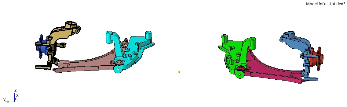
-but here we not seen perfectly lines on surfaces. for that we convert auto mode to topo mode.
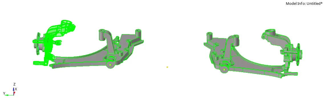
2) Creation of 3D meshing as per quality criteria:-
-the quality criteria of the model is:-.
Elements sizes:- Minimum length -2 mm,
Target length - 6mm,
Maximum length - 8mm
-now next step is create 3D meshing in the component.
-for that use tetra mesh command and choose components and create a mesh.
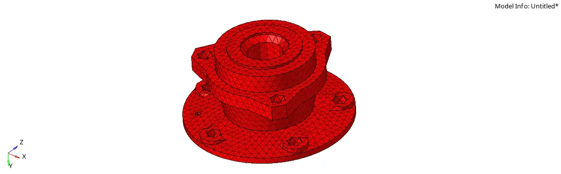
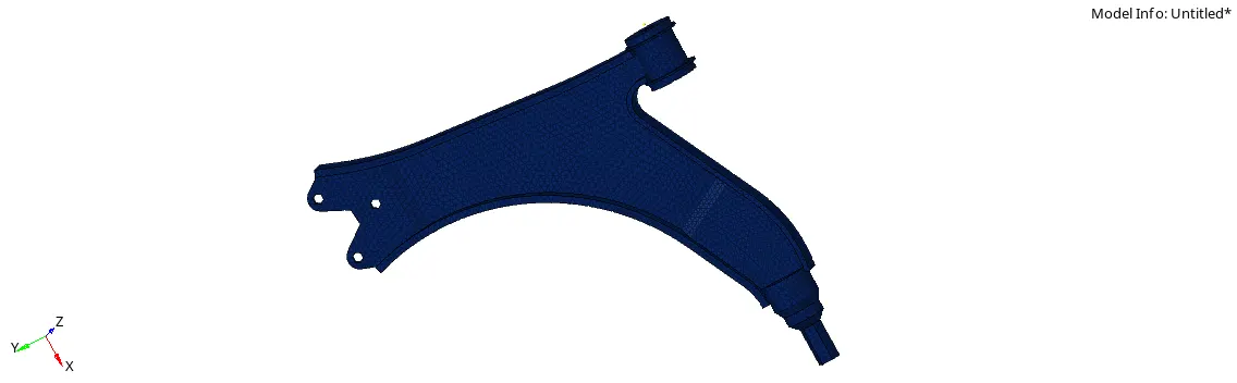
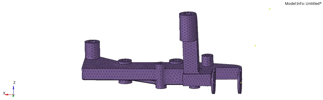
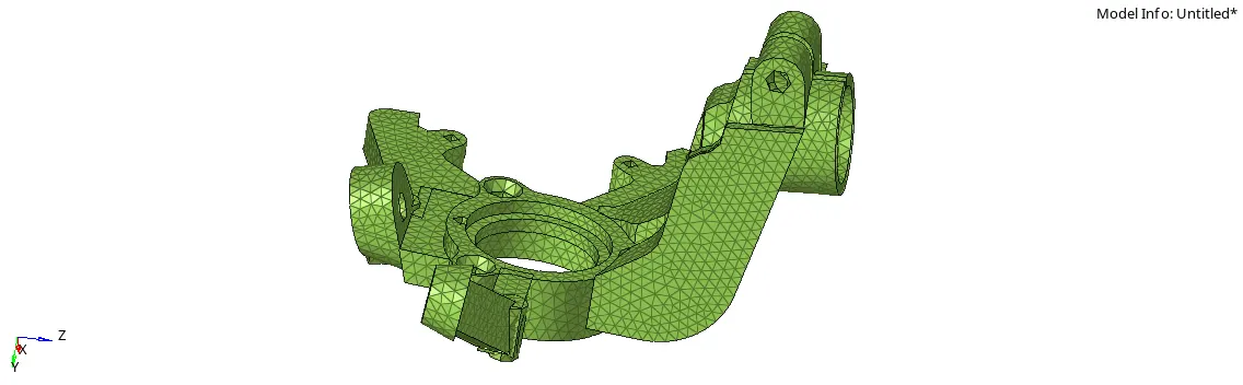
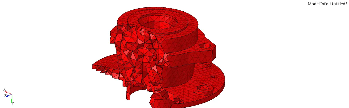
-but for this component we use volume tetra mesh for best result. (3D>tetra mesh>volume tetra)
3) Check 3D quality of mesh:-
-After generation of the volume tetra elements, we check the quality of mesh.
-the main important quality for 3D tetra meshing is tet-collapse.
-here value required of tet collapse is more than 0.15
-we remove tet collapse elemets by elements using translate command.(Tool>translate)
-otherwise, some time use tetra remesh command.(3D>tetra mesh>tetra remesh)
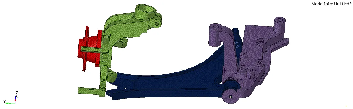
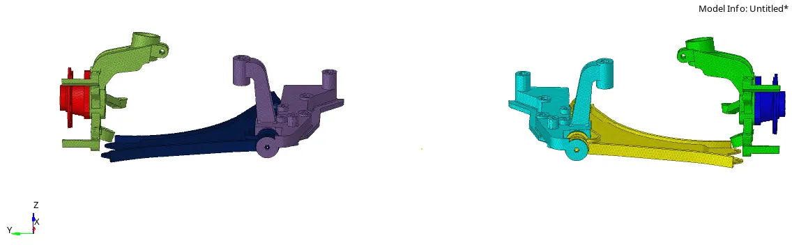
4)reflection of symmentric components:-
-after the meshing on every components next step is reflet to another side.
-reflect command is very important for save the time and less the work.
-for reflection we required to base point. then first of all create the base point at the centre.
-after the create base point, use refect command.(tool>reflect)
-here main important point is select curret component is which we are reflect.
-after the reflection:-
*conclusion:-
-the given every models are good as per quality criteria.