various connection techniques for frame assembly model using HYPERMESH software
*AIM:-
Mesh the model as per given quality criteria, after that crate connectors and attach various parts.
Model name:-
frame assembly
methodology:-
1)import the model
2)2D meshing as per quality criteria
3)connect various parts using connectors
1) import the model:-
-The format of the file is hm, then first of all select import solver deck command, choose import model and select file from our folder.
-after that choose import opction for import it.
-but it is not visible on our screen due to graphical issue , for that use f key and then its visible.
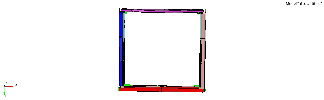
-here, we seen that thickness are not available for any surfaces; means we does not required to create mid suface.
-actually here directly provide midsurfaces.
2)2D meshing as per quality criteria:-
-mesh the every surfaces using following quality criteria:
Targeted elements length : 5 mm
Minimum elements length : 2 mm
Maximum elements length : 8 mm
-This values are provide in the criteria file setting.(preferences>criteria file settings)
-now mesh components surface by surface using automesh command.(2D>automesh)
-here, type of mesh is mixed for better results.

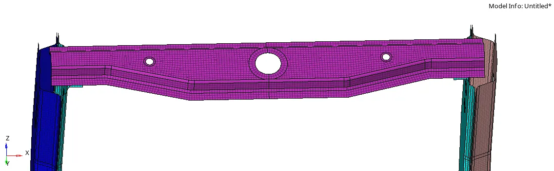
-for better results remesh the elemts by elements.
3)connect various parts using connectors:-
-after the create good mesh, the next step is attach the various components using connectors.
connectors are used foe connect two components.
a) Right_Rail_2 & Front_truss_1:- Seam-Quad(angled+capped+L)
-for that first of all select seam command.(1D>connectors>seam)
-here, provide this values:-
location:- node path
spacing:- 5mm (it is equal to our mesh size)
tolerance:-10
type:- seam+quad(angled+capped+L)
weld angle:- 45 degree
cap angle:- 75
run off angle:- 10

-After providing this value select the create opction, then produce seam welding.
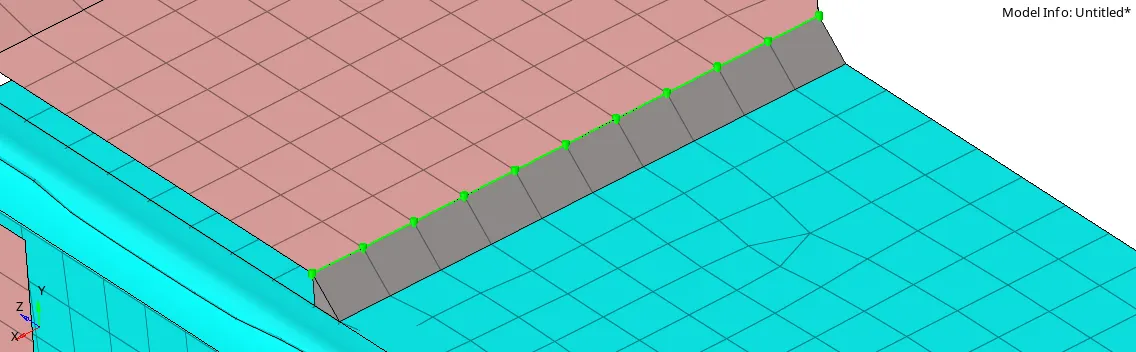
-this welding process also apply between this
Front truss 2 & Left rail 2
Front truss 2 & right rail 2
b) Left_Rail_2 & Front_truss_1:- Quad elements
-for that first of all select seam command.(1D>connectors>seam)
-here, provide this values:-
location:- node path
spacing:- 5mm (it is equal to our mesh size)
tolerance:-10
type:- quad

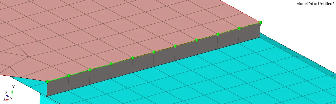
- this connectors are also use for:-
Front truss 1& reinf plate
Front truss 2 & reinf plate
c) Front_truss_2, Front_truss_1 & Right_Rail_1:- Spot weld with 3 Layers and 5 mm Diameter
-for that choose spot command.(1D>connectors>spot)

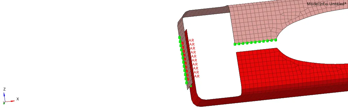
d)Front_truss_2, Front_truss_1 & Left_Rail_1:- Hexa (Adhesive)
-for that first of all select seam command.(1D>connectors>seam)
-here, provide this values:-
location:- node path
spacing:- 5mm (it is equal to our mesh size)
tolerance:-10
type:- hexa adhesive

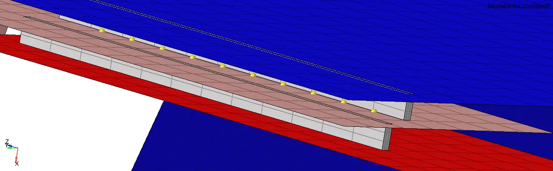
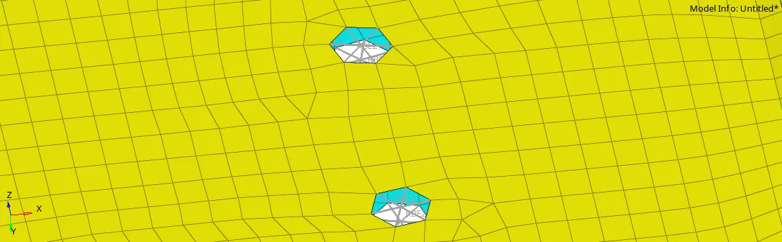
e)Rear_truss_2 & Right_Rail_2:- Bolt Connector
-for that choose bolt command.(1D>connectors>bolt)
f) Rear_truss_2 & Left_Rail_2:- Bolt Connector
-for that choose bolt command.(1D>connectors>bolt)
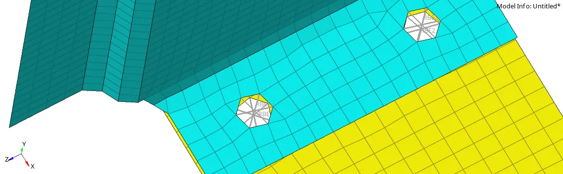
-it is also applied for this th:-
-rear truss 2 & right rail 1
-rear truss 2 & left rail 1
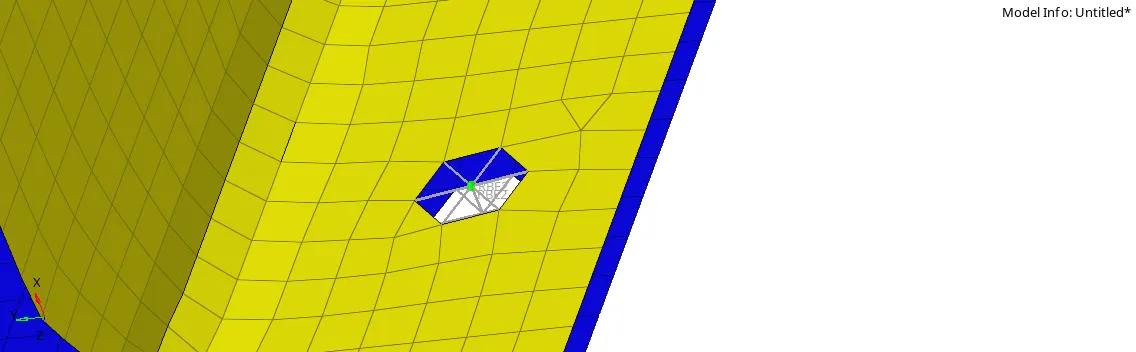
g)Right_Rail_1 & Right_Rail_2:- Spot-weld with Rigid Elements
--for that choose bolt command.(1D>connectors>bolt)
-here, provide this values:-
location:- nodes
spacing:- 5mm (it is equal to our mesh size)
tolerance:-10
type:- rigid

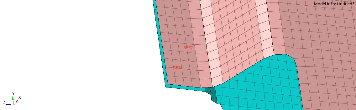
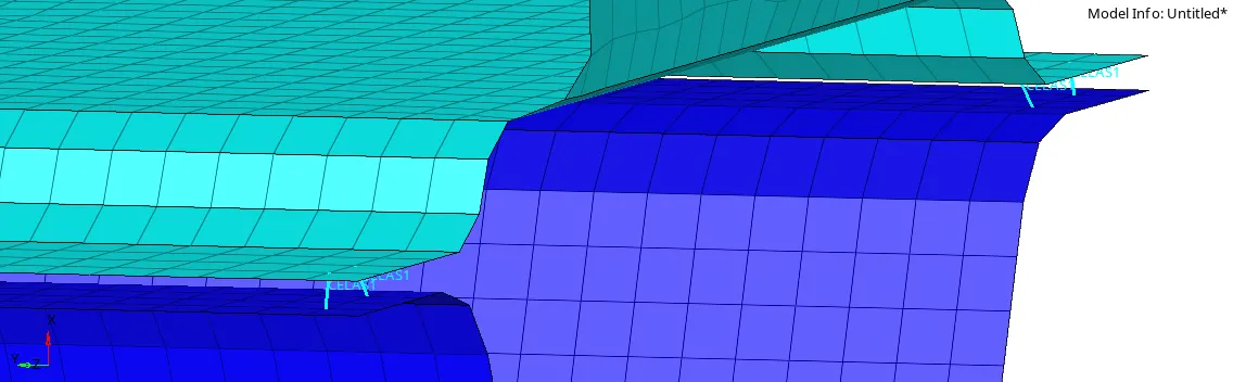
g)Left_Rail_1 & Left_Rail_2:- Spot-weld with Spring Elements
--for that choose bolt command.(1D>connectors>bolt)
-here, provide this values:-
location:- nodes
spacing:- 5mm (it is equal to our mesh size)
tolerance:-10
type:- spring

*Learning outcome:-
-we undrestand about how to connectors are use for connect two components