Week-6 Calculate the Stretch Ratio by comparing the ELFORM (-2,-1,1,2) with Ogden_Material Model.
Aim:
To create a solid block of 10*10*10 mm cube with ogden material model as given. And giving the strech ratio upto 5 , we have compare the results of Element formulations of 1, 2, -1, -2.
Explination:
- To create a Solid cube
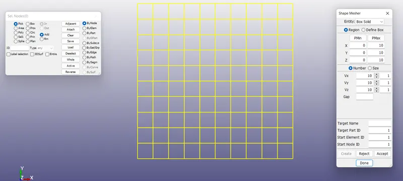
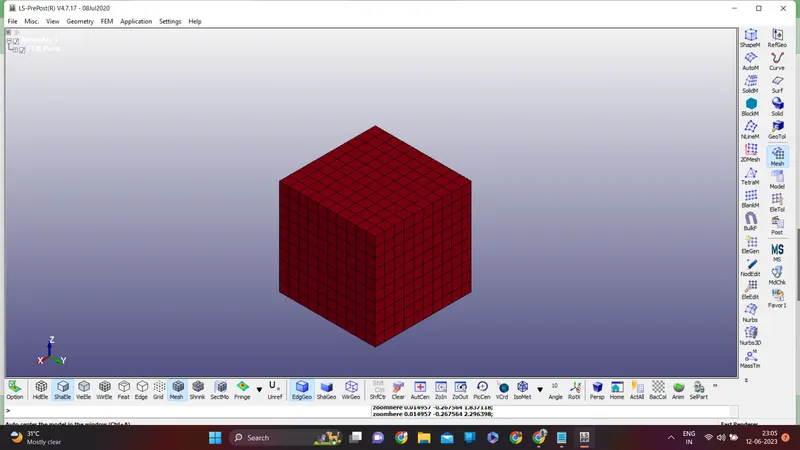
using the shape mesher in Elements and mesh create a cube of 10*10*10 mm
- Assign the ogden material as given to the cube
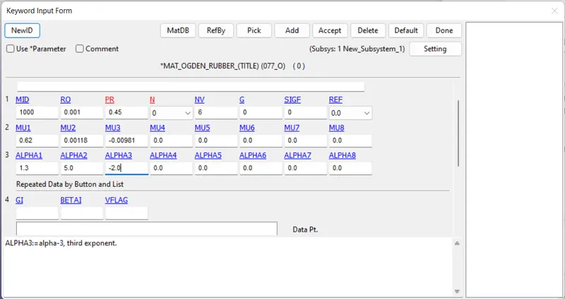
Using the material code 077 odgan material id created and the values are updated as given.
Here units are taken in gm-mm-ms. and the values will be same as given
- Creating the section
As it is solid. create the section solid as shoen below
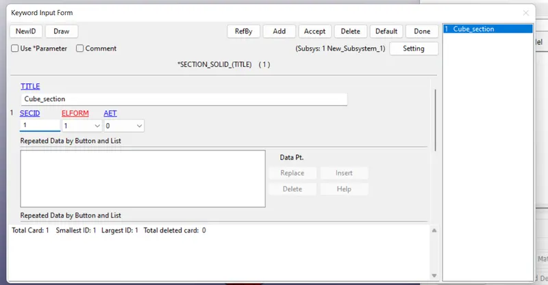
in this case I have started with the element formulation of 1. later 2,-1,1 will be updated.
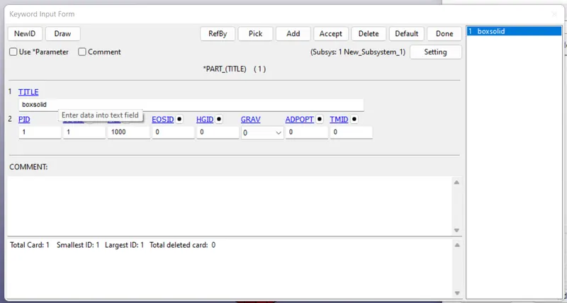
- Assign material and section to the part
- Apply the Boundary conditions
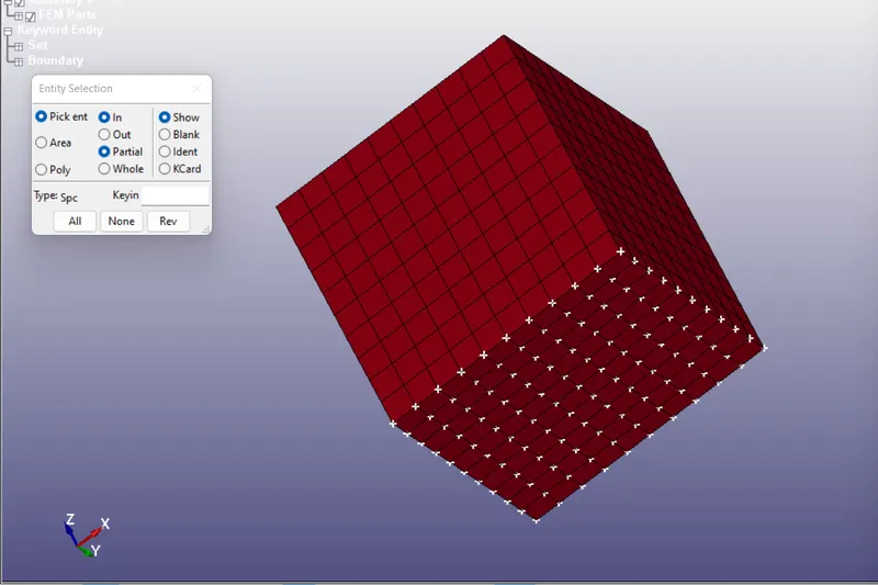
From the problem statment , only unaxial loading is applied. so the bottom of the cube to be fixed and apply motion to the upper face. And the material has to shrink in X and Y direction. so conidering that criteria
- Constrained the bottom face in Z direction and rotational around x,y,z (for all the nodes)
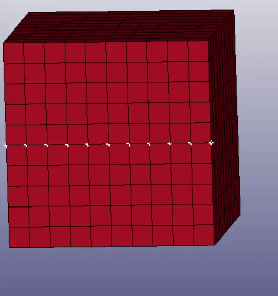
- Constrain in x direction : in this only middle nodes along x direction has to apply this as the rest of the part will shrink
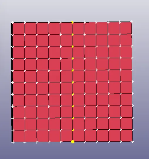
3. Constrain along y direction , same as the x direction
4. Apply the load
apply the load in the postitve z direction on the top nodes of the cube. for that we have to prescribe the motion card. Before we have to create the node set id for the upper face nodes and define the curve as below
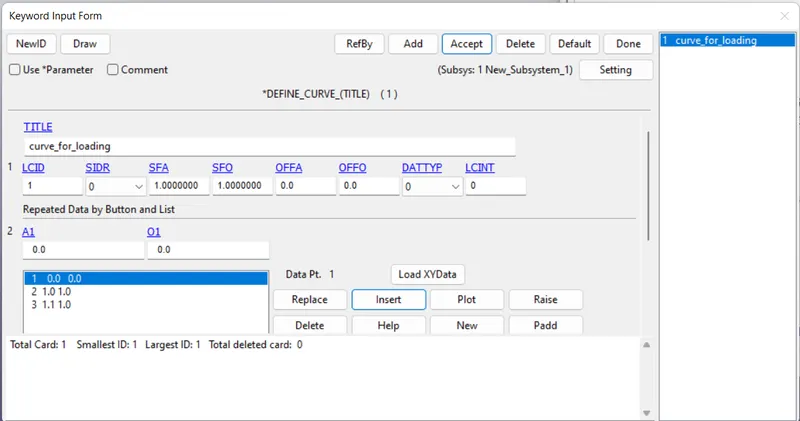
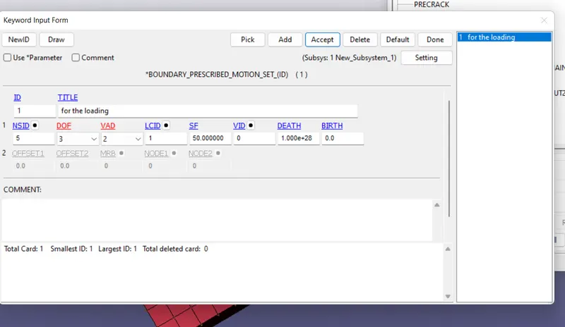
Now for the laoadinf it has give in the positive z direction. and the value is caluclated from the strech ratio. from the probelm given strech ratio 5 so the final length of the cube should be 50mm as the intial length is 10. so we have add 50mm as displacement. and then final Boundary prescibed node set is created as below
- Selecting the Solver
Here we can use the implicit solver. As the deformation is in one direction and happening in a gradual manner. unlike the explicit where deformantrion is large in a small amount of time. Here the material is a hyper elastic material so the strech 50mm is small. so implicit solver is the best option.
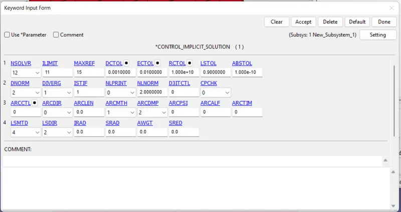
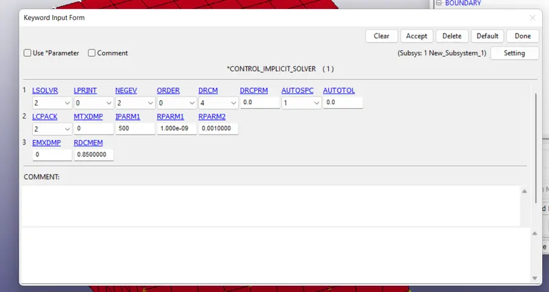
So the implicit control cards are defined
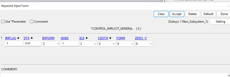
- Control_implicit_general
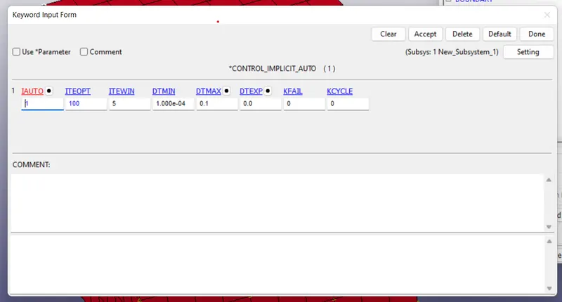
- Control_implicit_auto
- Control implicit Solution
- Control implicit Solver
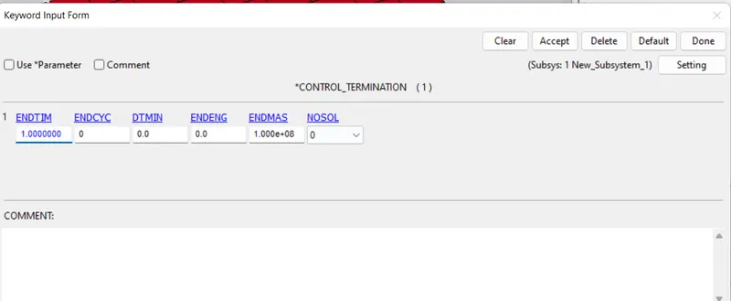
- Control termination
Apply the control termination woith end time as 1.00 as total step value. As we define the step value as 0.01 in control implicit general
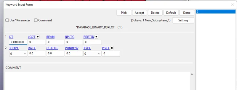
- Binary D3 plot
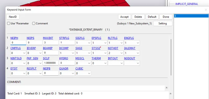
- Define the Database_extend_binary
Database_Extend_Binary card and activate the STRFLG to get the strain data
- Run the Program
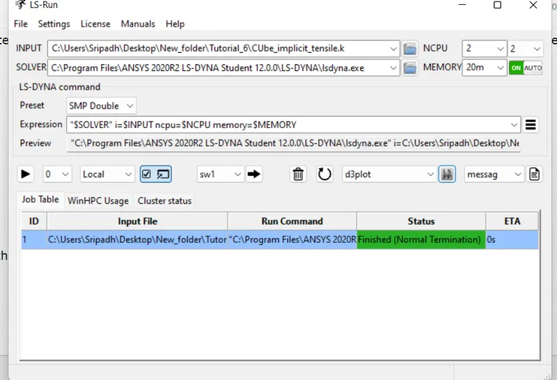
Similarly for the Element formulation -1, 2, -2
- Output
After running the simulation the results will be as follows
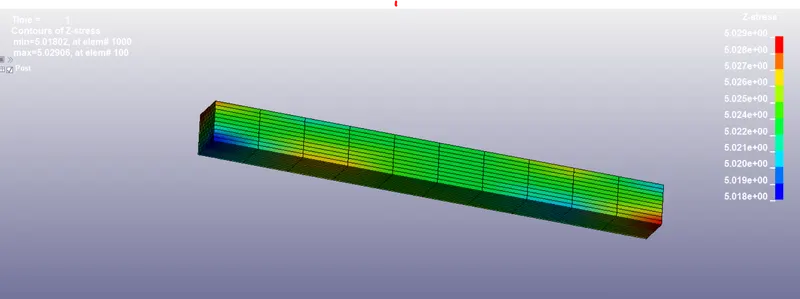
- Stresss contours
Element formulation 1
Element formulation -1
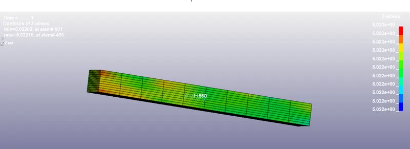
Element formulation 2
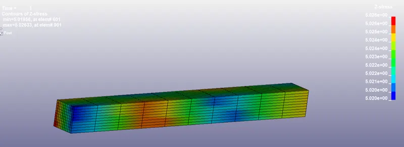
Element formulation -2
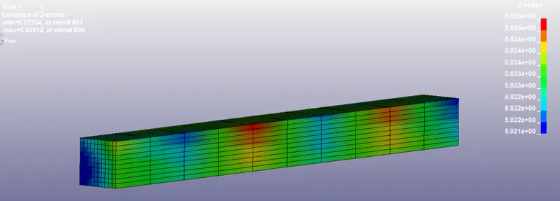
From the above we can see that all the element formulations have same max stresses. But the disturbution along the length is different
- Strain contours
Element formulation 1
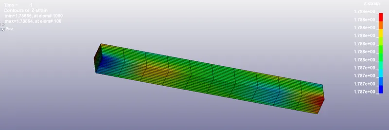
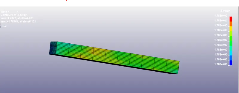
Element formulation -1
Element formulation 2
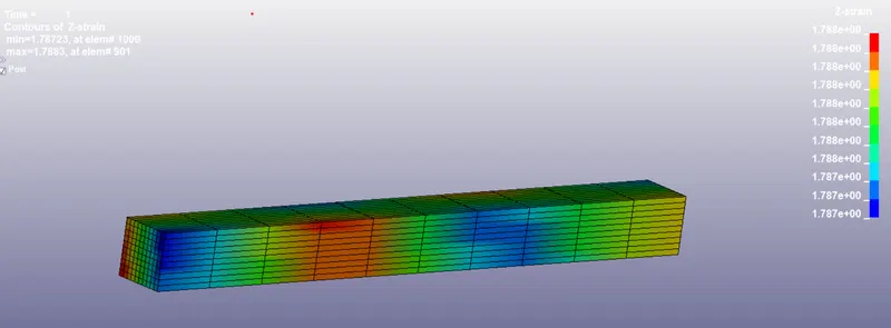
Element formulatio -2
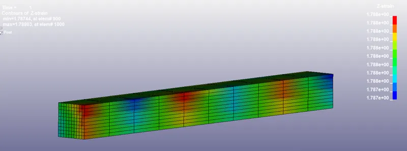
Form the above we can observe that the maximum strain in all the cases are almost same. This is due to the uniaxial loading and all other conditions are same.
- Nominal Stress & Strech ratio curves
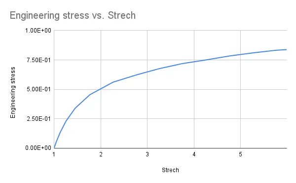
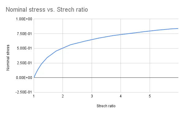
From the LS Pre post we get the true stress and true strain. from that we can claculate the engineering stress and strech ratio
Strech ratio (λ) = exp(true strain)
Engineering stress = True stress / λ
therefore by calculating the above and plotting it we get the curve as follows
Element formulation 1
Element formulation -1
Element formulation 2
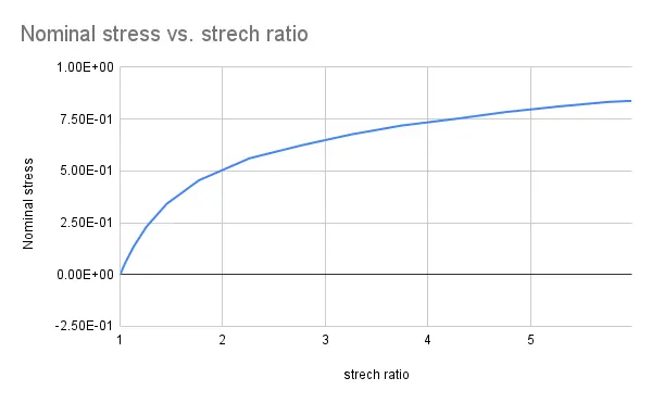
Element formulatio -2
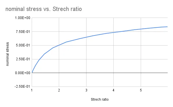
From the above graphs we can say that all the strech ratios & Nominal stress are same for different element formulations.
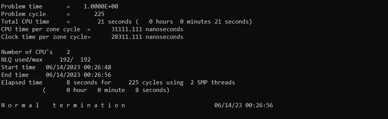
- Runtime
Element formulation 1
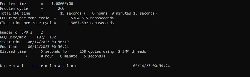
Element formulation -1
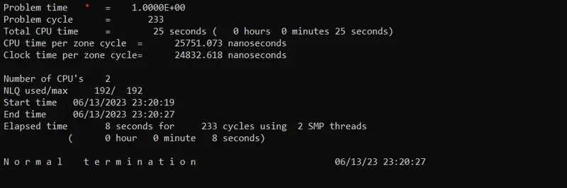
Element formulation 2
Element formulation -2
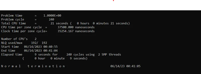
From the above image , we can observe different computational time and cycles for different element formulation. we can see that elemenr formulation -2 is taking the highest time for computation. And for cycles Element formulation 2 is taking the lowest one.
- Conclusion
we have obsereved that almost same results for different element formulations. This is due to the unaxial loading & also the material is hyper elastic where the deformation is not too large.