Week - 4 - Crash Box Simulation
Aim
The Aim of this anlysis to specify the crash box Simulation. mesh file of crash box is given, we have to create a Rigid wall using rigid wall keyword. And then assign the material and section to the crash box.And then define velocity of crash box and contact to the rigid surface. And define the specfic outputs as mentioned above.
Explination:
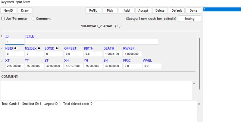
- Create a Rigid wall
In this I used Rigid wall Planar. It is defined with using create entity rigid wall planar. And by selecting 3 nodes on the crash box for refrence for plane creation. and then giving offset of 5mm to it
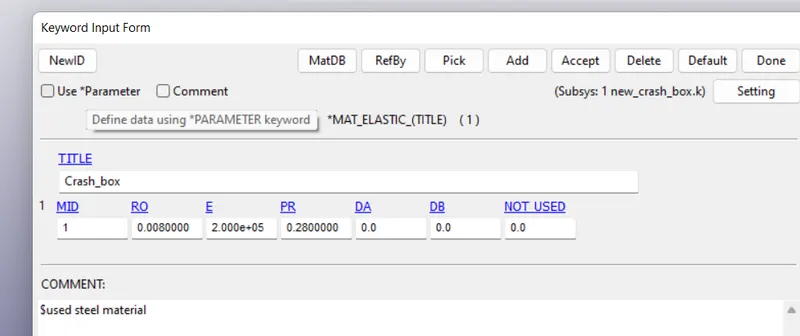
- Creating Material id for Crash Box
From the problem statement , it is said that crash box is made up of steel. and to exhibit the elastic properties. so used the MAT_01 Elastic material is used as is defined as below. The unit system mentioned is gm-mm-ms. So all the properties are converted according to it.
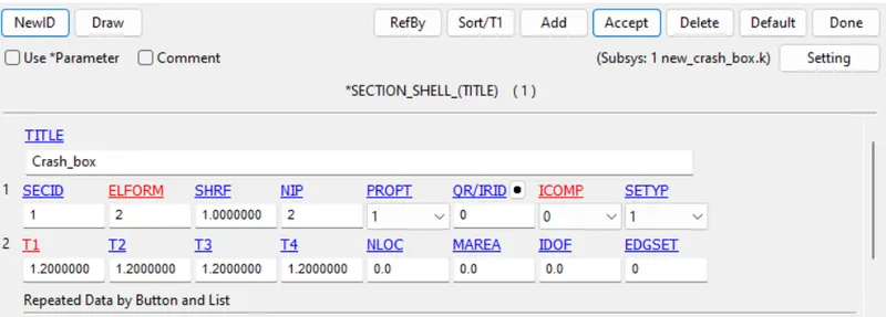
- Creating Section id for crash box
In this Section shell keyword is used. section id is defined and added a thickness of 1.2mm. and uses the element formulation of 2. it is as defined below
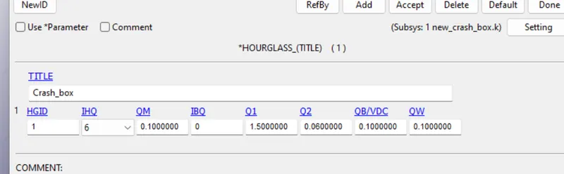
- Creating hourglass
Hour glass is created with hour glass type 6 as the crash box is made up of shell. And hour glass coefficient as 0.1 as the material is elastic.
- Assigning Material ,section and hour glass to the part
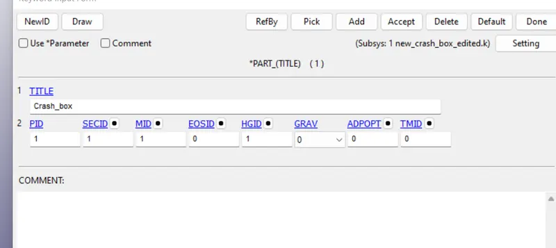
- Creating a node set id of crash box
For applying initial velocity, we have to create a set id of crash box. so it is created using create entity
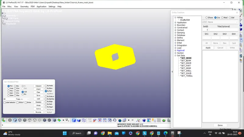
- Apply initial velocity to the crash box part
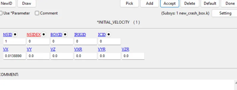
Initial velocity is given around 50 kmph. it is converted and added into the initial velocity keyword. And the direction is along postive X direction aganist the rigid wall
- Adding Control Termination
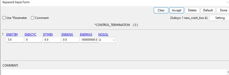
Control termination is added with the end time of 3ms.
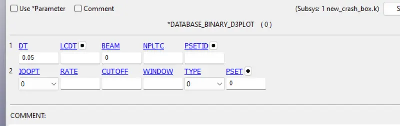
- Database D3 Plot
Apply D3 Plot with Time interval of 0.05ms.
- ASCII Plot
In ASCII Option GLSTAT, RCFORC, SLEOUT are mentioned with a timeInterval of 0.05ms
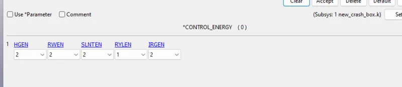
- Control Energy
Updated control energy with HGEN (hourglass), SLEN (Sliding)
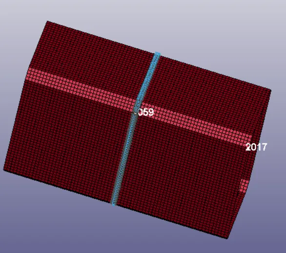
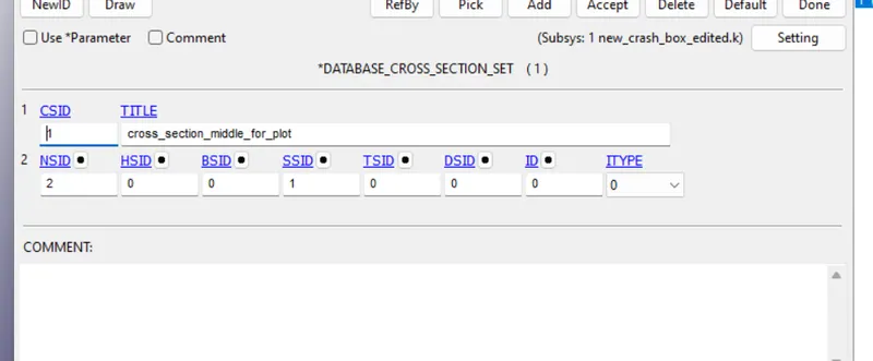
- Cross Section Plane creation for SECFORC
for this option we have to create first Node set Id and Shell set Id for refrence of mid plane and it is shown as below. and assign it in the Database cross section set
- Run the simulation
save the keyword file and run the simulation for the results
- RESULTS
- Input Files
FOR 1.2MM THICKNESS
Keyword : https://drive.google.com/file/d/1NCacFT9Yy6bEUUt-CW-oqEKPveUx3FGc/view?usp=sharing
glstat: https://drive.google.com/file/d/1mNeqbIJlqB0r32Zz-tomm7PVla2DAfHW/view?usp=sharing
sleout:https://drive.google.com/file/d/1vQU3qaeFfTO1PW1RSl90utM-J_yEuX_F/view?usp=sharing
rcforc:https://drive.google.com/file/d/1N9m5wIorwQzpDoGxgBlnNw-Fd-o4TC0g/view?usp=sharing
FOR 1.5MM THICKNESS
Keyword: https://drive.google.com/file/d/15KA3nSgkx1knYC6LwM3KCJ5YwXjsihfm/view?usp=sharing
glstat:https://drive.google.com/file/d/1esHcKJ0iYEL2RuODFUFGi4SAx9GssT87/view?usp=sharing
sleout:https://drive.google.com/file/d/18FwE_-yowuAKSvP53jk-OINTCT3XegBB/view?usp=sharing
rcforc:https://drive.google.com/file/d/1418M9-d1F-wBAM1qgidkOepNRU5LyEml/view?usp=sharing
- Simulation
After running the simulation,Here i got the case that the crash box rebound completely after crashing the rigid wall. And the animation of final simulation is submitted below
Video link: https://drive.google.com/file/d/1ekQ3cRnVST5LnQ9lTm1WyaOK7_41s6BI/view?usp=sharing
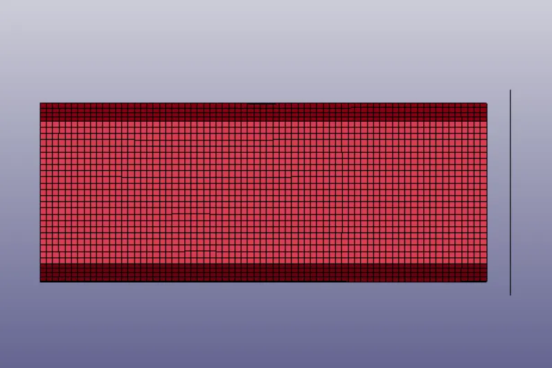
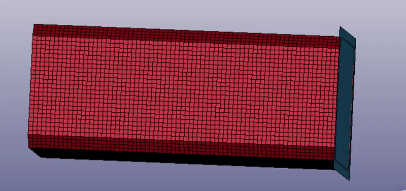
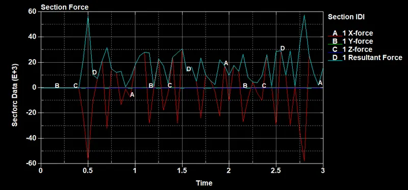
- Cross sectional force genrated in the middle of crash box
The graph was plotted and it is as shown below
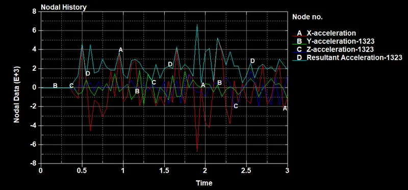
- Accleration part of the node along the middle of crash part
The middle node of the part is selected after clicking on the history tool. and then plotted the x, y ,z and resultant accleration. The graph is shown as below
- Maximum directional stress and strain along the length of the crashbox
Here maximum directional stress & Strain is along the X direction.So mid element is selected and plotted the stress and strain courve. It is as shown below
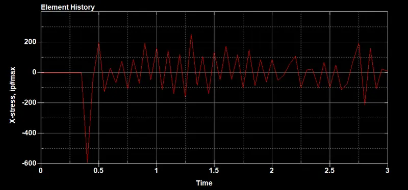
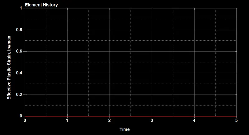
Here there is stress but no strain is showing zero. the reason is due to because it is a elastic material and there will be no plastic strain on it.
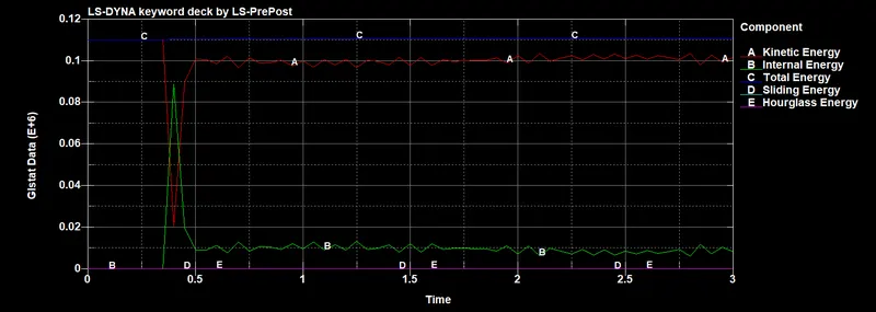
- Plot of all energies (total, internal, kinetic, hourglass, sliding)
The observation you can see is that, there is variaition in KE and IE at the contact. Total Energy is almost same and Hourglass energy and sliding energy is almost zero
- Compare the accelerations and stress/strain plots of 1.2/1.5mm crashboxes
Acclerations comparison
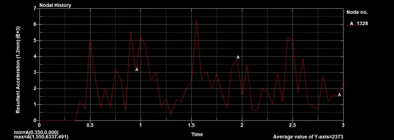
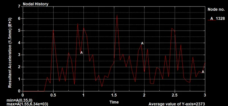
By comparing the results we can say that , the acclerations results are almost same.
Stress Comparision
Stress comparision for same element 1176 is as below
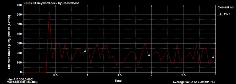
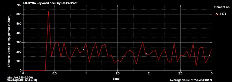
Stresses are also same in comparision.
Conclusion:
Here we analysis the crashbox simulation. with taking various parmeters, we were able to analysis the energy, stresses& strains, foprces and acclerations. also comparing the between thickness of 1.2mm and 1.5mm