Week - 5 - Modelling Spotwelds
Aim
The Aim is create a spot weld using beam and solid type. and do the crash test to check the failure. And then compare the results between the beam spotweld and solid spotweld.
Explination
1. BEAM SPOT WELD
- Node set creation
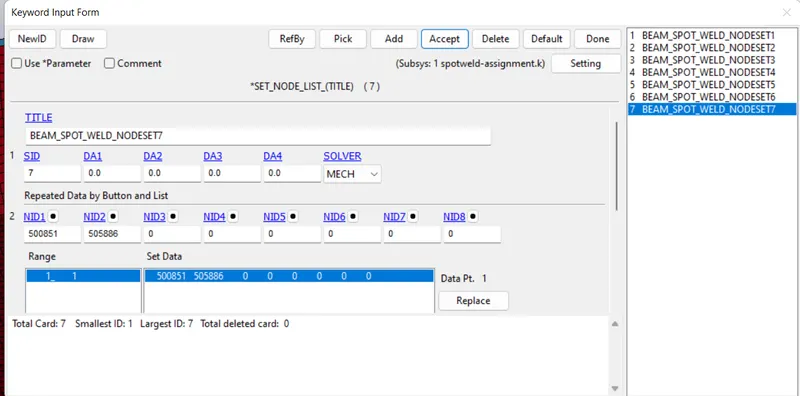
In this I used of 7 spot weld across the length. So for that 7 note set ids was created in the same line
- create constrained spot weld
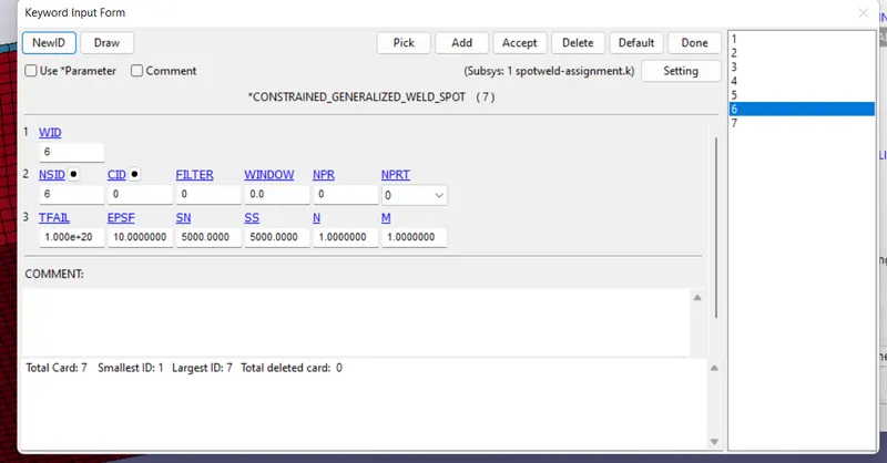
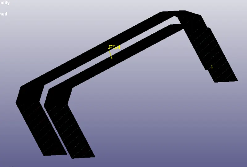
Assign the above created node set id to this keyword to create 7 spot welds
- create Section
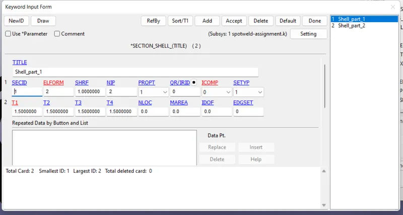
Section id is created for both shell parts with element formulation of 2 and thickness of 1.5mm.
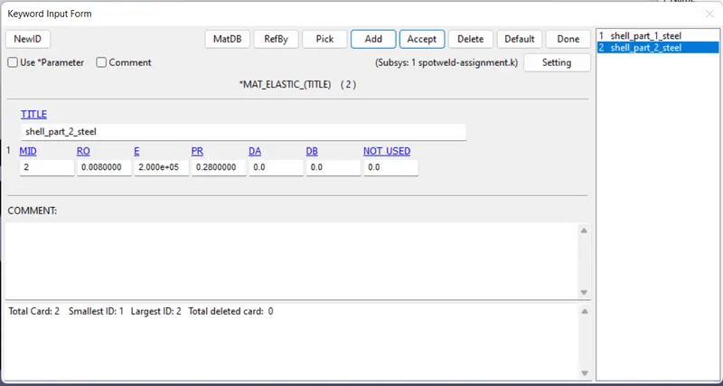
- Material creation
For the case of simplicity , we use elastic material i.e, MAT_01 for shell parts. steel material is used and all the values are taken in gm-mm-ms
- update part
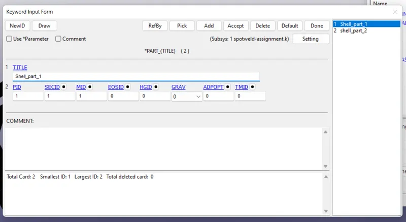
Assign material and sectionof shell elemts to the part. as shown below.
- Create Rigid wall
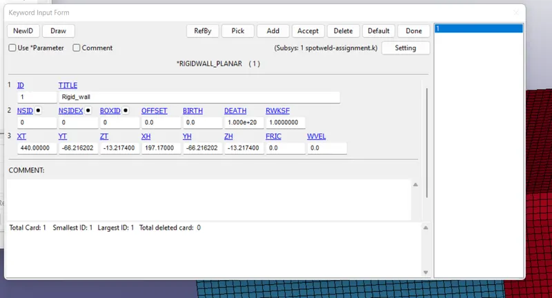
rigid wall is created in x direction with npormal opposite to it for crash simulation. and the gap between is taken as 40mm.
- Create Initial velocity
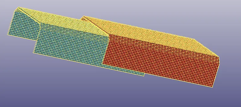
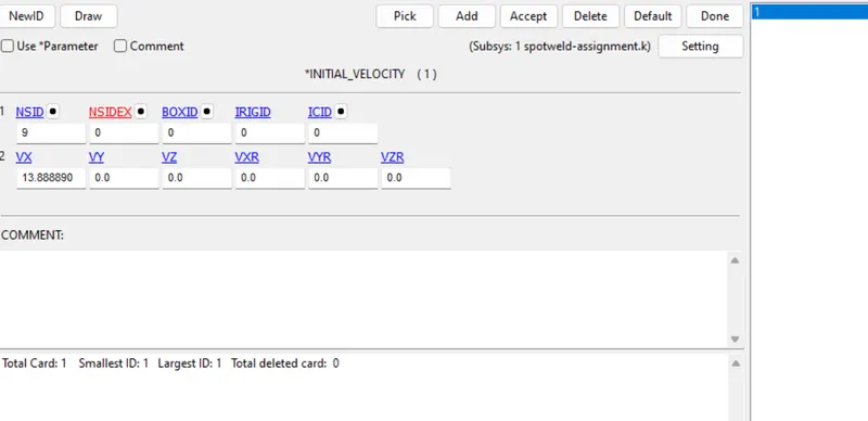
Give the intial velocity of 50kmph to the part. and by converting it inot gm-mm-ms it has 13.88889 mm/ms. and it is applied to node set created as shown below
- Contact Automatic single surface
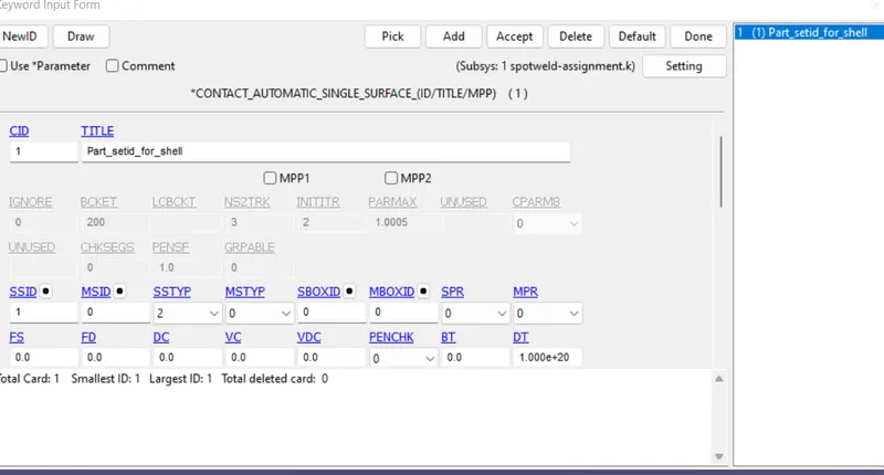
create automatic single surface contact between shell parts to avoid penetration after crashing.
- Control Termination
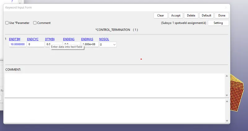
time period to run the simulation is given 10ms.
- Datebase binary D3plot and ASCII options
all the D3plot, glastat, swforc, nodout has to be created with time intervak of 1ms
- Database History node set id
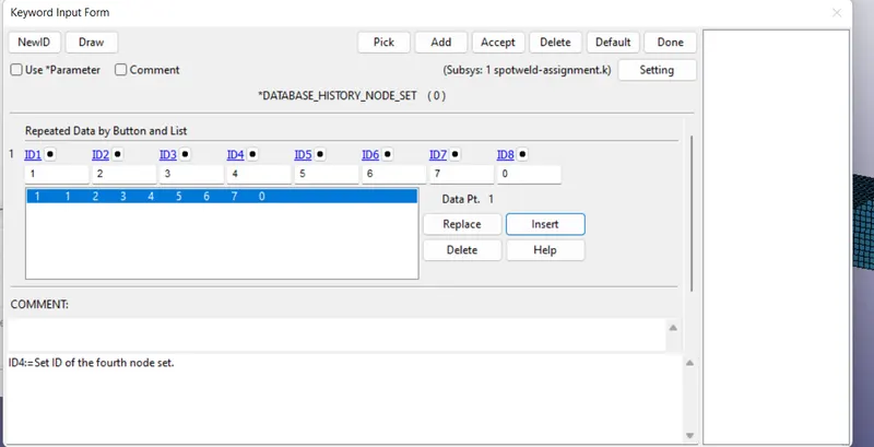
it is created to define node output partmaters of beam spotweld. The 7 node sets has been inserted in it.
- Run the simulation
after running the simulation. we can check the video that , after contact with the rigid wall , we csn see that all 7 spot weld fails.
Video: https://drive.google.com/file/d/1suCr67simyneIUUXGKwK0LJnp6ikpWTe/view?usp=sharing
- Results
Keyword file: https://drive.google.com/file/d/1DziRh1Y84M-gtUa1l8_jIEI9W-kpY3TM/view?usp=sharing
1. Swforc
- Axial force & Shear force of Spot weld
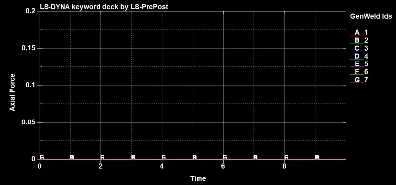
Here the axial force is almost zero in all the cases , as spot weld is failed mostly due to the shear forces. THe graphs are shown as below
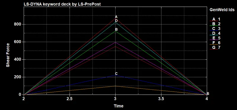
Here the max shear force is around 855 gm.mm/ms2
2. SOLID PART SPOT WELD
- creating solid spot weld
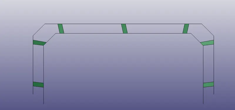
Spot weld solid part has been created using the element tools from the element editing using hexa material. and it as ahown below
- Assign the material
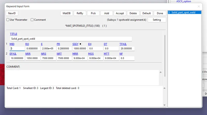
for the solid part MAT_100 spot weld has been used.
And the properties has to be highest value and then update the time failure as 3ms at starting to know about the axial and shear forces. and the values are 1010 & 7300 repectively. Now once again open the mat-100 to change the limits of Axial, shear and resultant force to the above values near by. And increase the failure time. After doing that it is as shoen below
- Assign the Section
As MAT-100 is used . So Element formulation of 1 is used as shown below
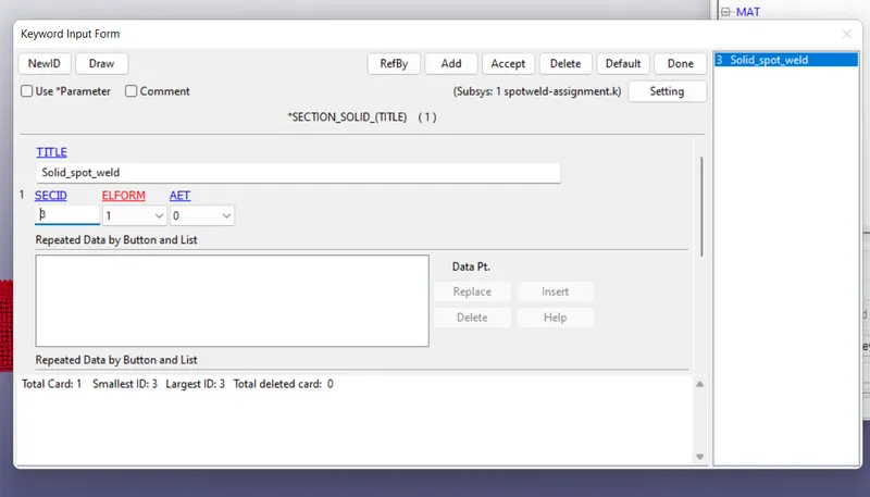
And rest of the parametes are almost same and after running the simulation we got the model as followa
Video link : https://drive.google.com/file/d/1tD0VBV_rx2mrqVYm9ePcpVSVbxNxgrPt/view?usp=saring
Keyword file: https://drive.google.com/file/d/1bpFrazRTDlLIUEjQNIv5f80qvOjw6Ih1/view?usp=sharing
- Results
1. Swforc
The results for Shear and axial force of the spot wled is as follows
Same as the beam weld here axial force is zero and the shear force is almost same , here it is 871 gm.mm/ms2
- CONCLUSION
Here we checked both the beam type spot weld and solid type spot with almost same parameters. here we can see that it has got almost same results, with solid part has slight edge over it and give better results and accurate.