Week-6 Calculate the Stretch Ratio by comparing the ELFORM (-2,-1,1,2) with Ogden_Material Model.
Calculate the Stretch Ratio by comparing the ELFORM (-2,-1,1,2) with Ogden_Material Model
AIM:
Create a block of 10mmx10mmx10mm dimension with 10 elements for each direction and use the material card attached (Ogden_Material.k) that is representative of the material properties from the above figure.
Use appropriate boundary conditions to simulate tensile behavior for the model and finally compare the results from your simulation to the plot above up to stretch ratio 5. Only the uniaxial plot is to be compared.
Compare the results for the simulation using ELFORM = 1, 2, -1, -2
The unit of µ in the material definition is in MPa and α is a dimensionless quantity. Modify those quantities according to your unit systems.
Use a proper solver (Implicit/Explicit) and also explain the reason.
PROCESS:
- Download and open into LS-Dyna
- It already has the material as shown ,thus assigne it to the part that you built
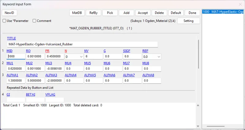
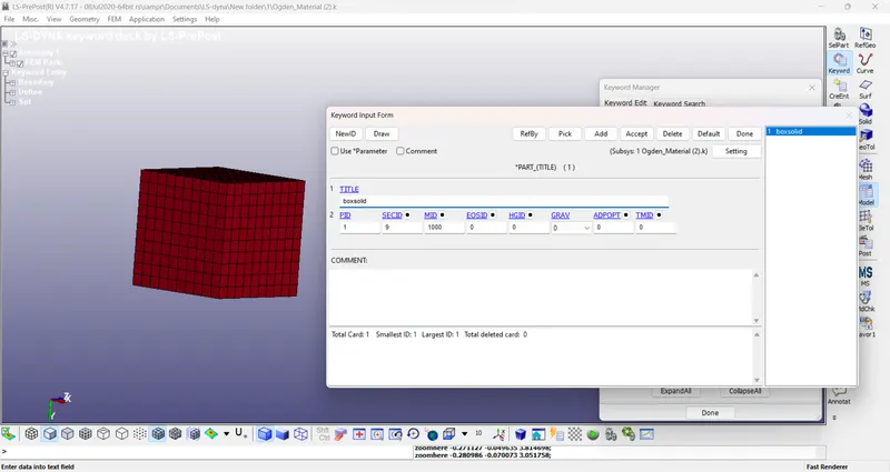
- Go for mesh and create box as per dimension
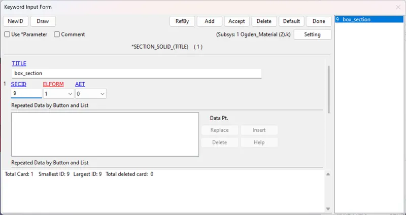
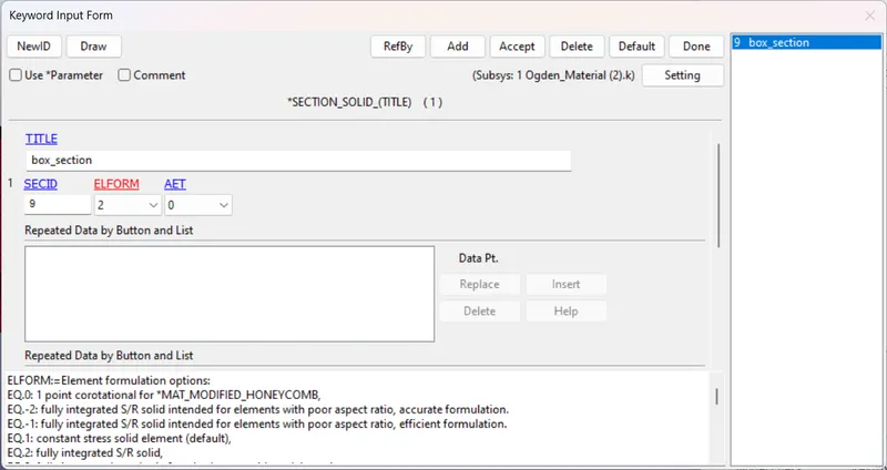
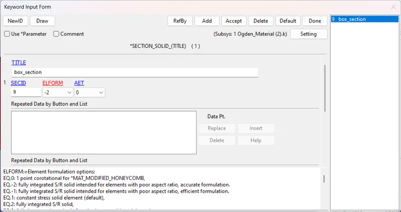
- Create section
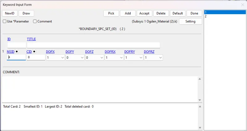
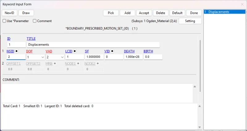
- Fix one end & at other end prescribe the motion as displacement
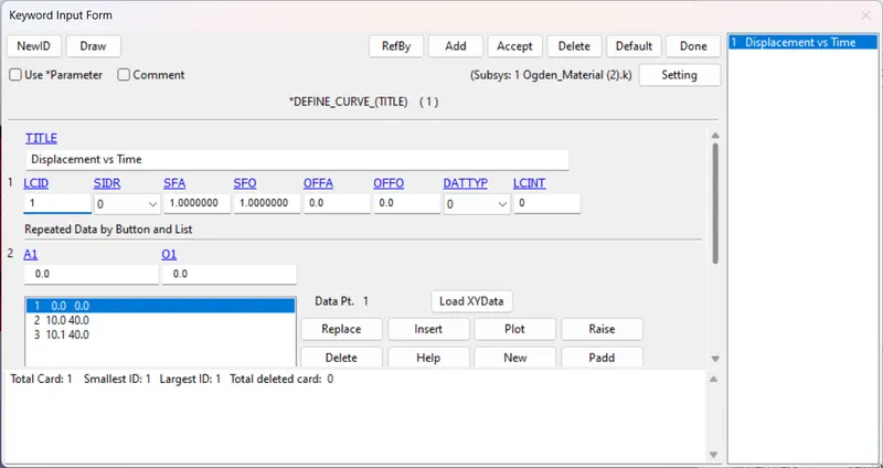
- Using define_curve give dimension of value
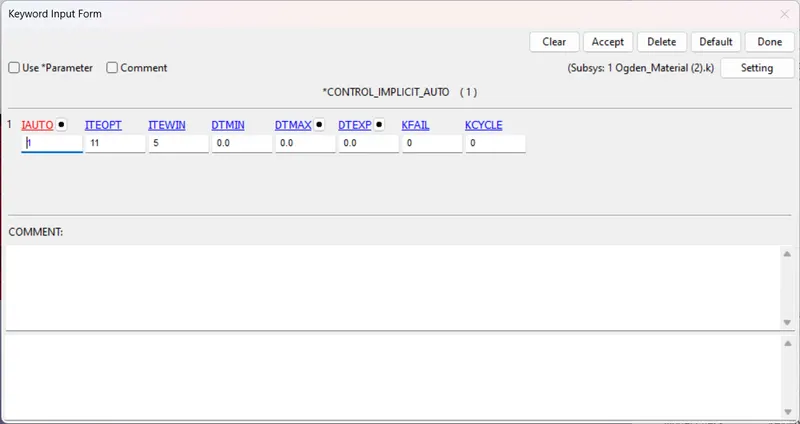
- As we are going with implicit give Implicit auto General
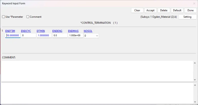
- Provide termination time
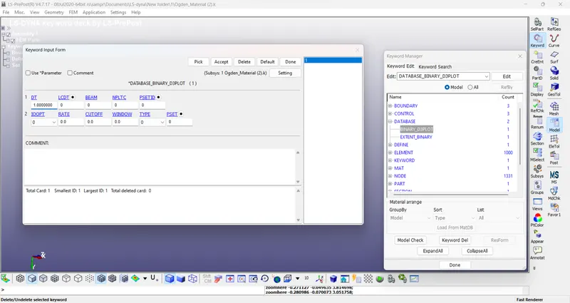
- Define the required outputs in Database As Binaryd3plot & Extend Binary
- Go For LS-Dyna RUN for solution
RESULTS
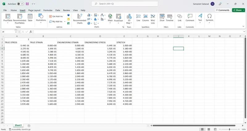
Excel sheet link: https://docs.google.com/spreadsheets/d/1EfvS4O7T37WpZrdUtJSZE-co9GN3cCjdEzf5dH0cGFk/edit?usp=sharing
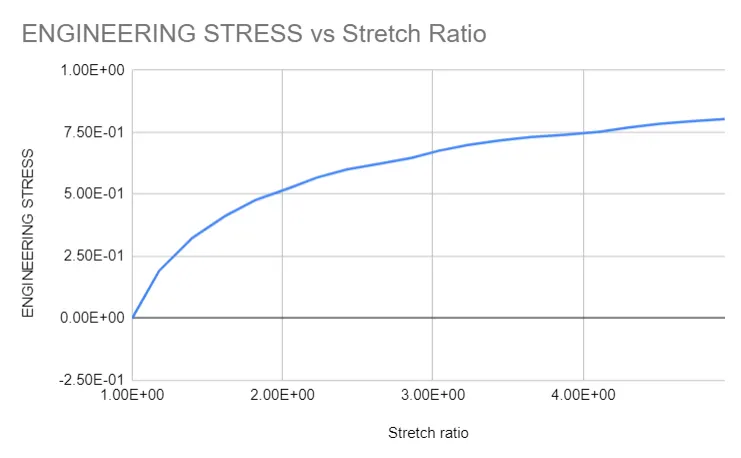
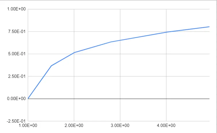
CHART of Engineering/Nominial stress vs Stretch
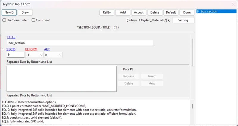
For other case change the section ELFORM as given
- Elform WITH -1
- RESULTS
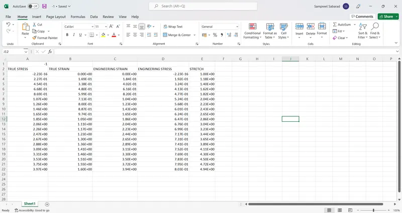
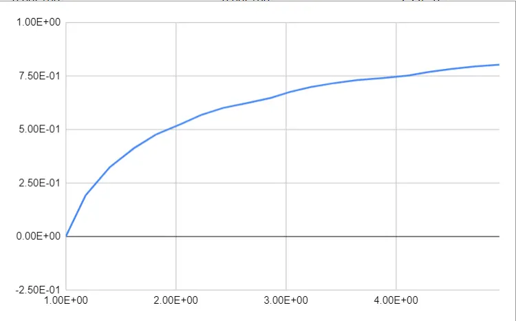
Excel sheet link: https://docs.google.com/spreadsheets/d/1NPUI2_oK1v_2K1m_IYBCZUxbViu0QHXe3IWngqHsV98/edit?usp=sharing
CHART of Engineering/Nominial stress vs Stretch
- Elform WITH 2
- RESULTS
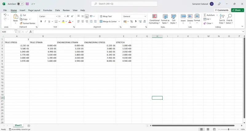
Excel sheet link: https://docs.google.com/spreadsheets/d/1xJNnnJnlx2W2DyHyyAZB2Q2guh7kRZ46hidnjJ7Sam4/edit?usp=sharing
- CHART of Engineering/Nominial stress vs Stretch
- Elform WITH -2
- RESULTS
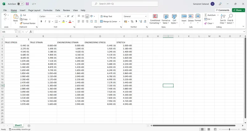
Excel sheet link: https://docs.google.com/spreadsheets/d/132FU8dJcXqXsmZ6qlN9D98FIPsOsz559EKLRi3D_o6w/edit?usp=sharing
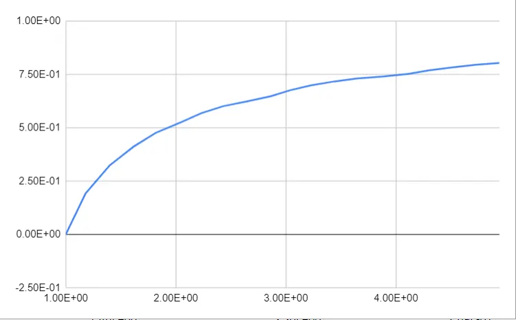
CHART of Engineering/Nominial stress vs Stretch
CONCLUSION
- THE model of solid block was created with ogden material to simulate uniaxial tension test for different cases
- As stretch increases the stress induced on the part model increases. We can notice a huge deformation in the hyper elastic material even after the yeild point while this cant be seen in other materials. We can aso visualize that the deformation occurs in an non-linear manner since the change in stress is not linear to the change in strain.
- The Engineering stress/strain and stretch ratio was calculated to plot a graph of Engg. stress vs stretch ratio up to stretch ratio 5
- Solid formulations -1 and -2 employ an assumed strain approach to avoid the shear locking behavior seen in formulation 2 elements that have poor aspect ratios.
- Solid formulation 2 most often employs a B-bar method and thereby assumes that pressure is constant throughout the element to avoid pressure locking during nearly incompressible flow.
- Constant stress solid element: default element type.By specifying hourglass type 10 with this element, a Cosserat Point Element is invoked;
- The Engineering stress value for a stretch value 5 from the simulation for different ELFORM was approximately equal to7 MPa, but from the actual graph it was equal to 1.8 MPa with a difference of 0.1 MPa
- The uniaxial tension test was solved using implicit solver since the analysis is similar to a quasi-static analysis on a hyper elastic non-linear material with slow steady loading conditions.