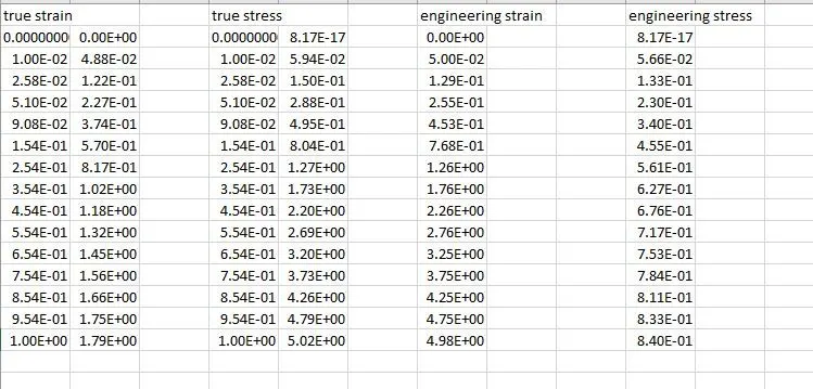
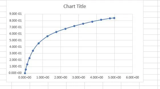
Week-6 Calculate the Stretch Ratio by comparing the ELFORM (-2,-1,1,2) with Ogden_Material Model.
Aim:
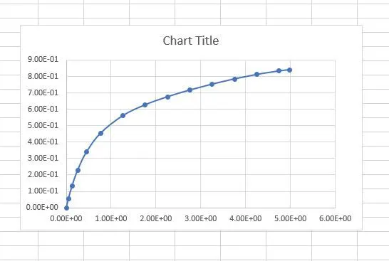
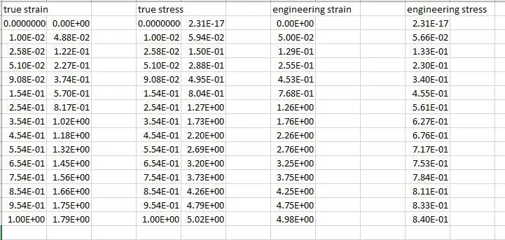
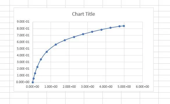
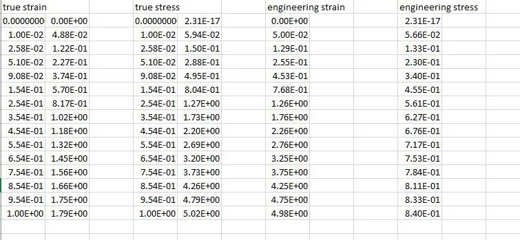
To Create a block of 10mmx10mmx10mm dimension with 10 elements for each direction and use the material card attached (Ogden_Material.k), And Simulate Using appropriate boundary conditions, and Compare the results of the simulation with ELFORM = 1, 2, -1, -2 by plotting Engineering Stress vs Stretch Ratio up to stretch ratio 5. With Necessary solver (Implicit/Explicit).
Introduction:
An Ogden model is a hyperelastic material model that can be used for predicting the nonlinear stress-strain behavior of material such as rubber or polymer. Ogden's model has introduced Ogden in 1972. The Ogden model has been frequently used for the analysis of rubber components like O-ring and seal. Even though the Ogden model is a hyperelastic material model, its strain energy density function is expressed by the principal stretch ratio.
Procedure:
The given LS-Dyna keyword file is opened in LS-PrePost using the option File>Open>LS-Dyna Keyword File. The imported keyword file consists of only the Ogden material card as shown in Figure1
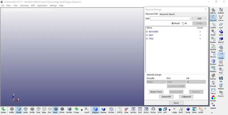 Figure1
For Modelling Cube Open Mesh > Shape Mesher, IN the Shape Mesher Choose Box solid As Entity> Dimensions as 10*10*10 as shown in Figure2
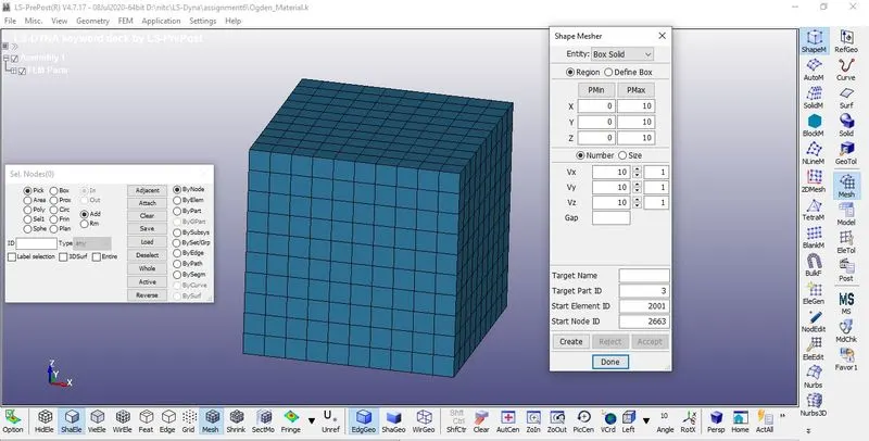
Figure2
2. Section Creation:
1. For Defining Section Go to Keyword manager > All > Section > Shell
2. For the Box, Section_Solid is created as shown in Figure3
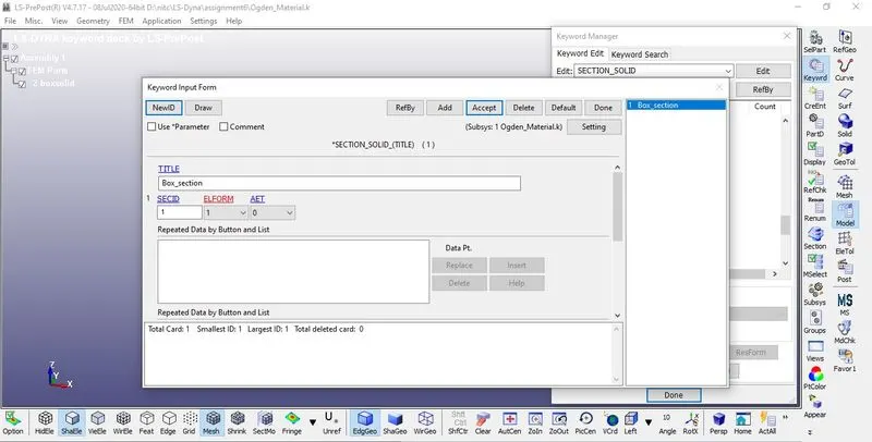 Figure3
3. Four different Element Formulations Are used To Solve the Problem, Element formulations (-1, -1, 2,-2) Are used Individually.
4.In this Case ELFORM=1 is Used ELFORM=-1, 2, -2 is used Consecutively for the Next cases.
Case (1). ELFORM=1, constant stress solid element.
Case (2). ELFORM = -1, Fully integrated S/R solid intended for elements with poor aspect ratio, efficient formulation.
Case (3). ELFORM = 2, Fully integrated S/R solid
formulation.
Case (4). ELFORM = -2, Fully integrated S/R solid intended for elements with poor aspect ratio, accurate
3.Assigning Materials:
For Defining materials go to Keyword Manager> All> MAT > Select the Material card. Here The Material MAT_077_O-OGDEN RUBBER Is given in the keyword file so it is assigned to the Box as shown in Figure4
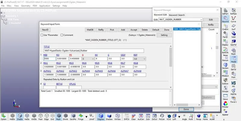 Figure4
4.Specifying the Material and Section ID to the respective part IDs.
1. In parts, we basically assign material and sections with their proper ID for every part individually.
2. Assign the Section Id and Material of the box in the Part as shown in Figure5
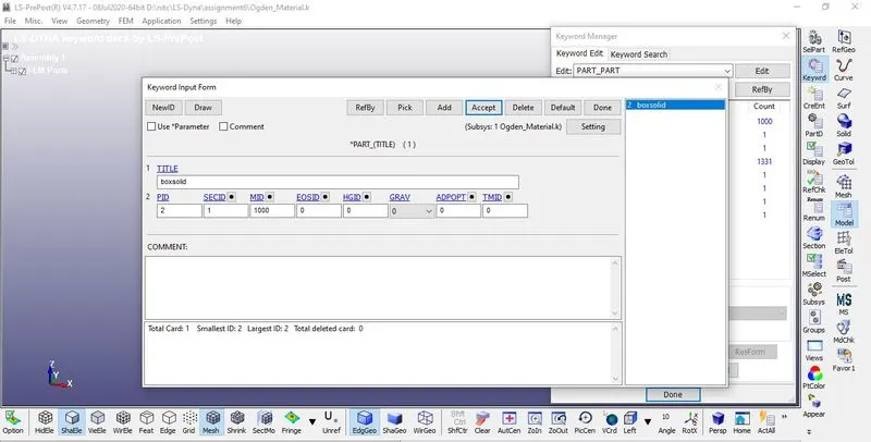 Figure5
5.Boundary conditions:
Tp perform Uniaxial Tensile Test On the specimen The Nodes Of One of the Faces Are fixed Using SPC as shown below Figure6,7,8,9,10&11.
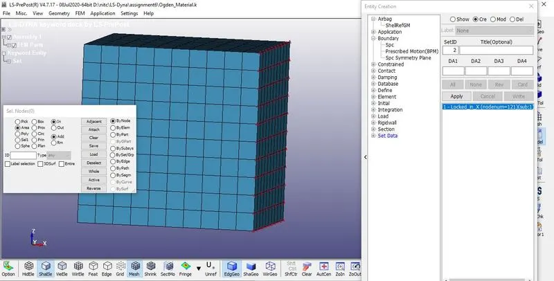 Figure6
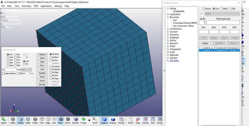 Figure7
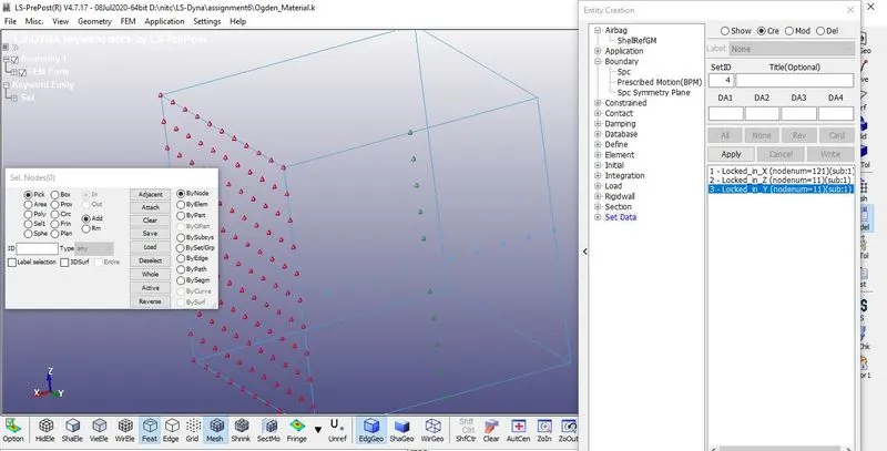 Figure8
Select The Nodes in the Middle And Dof's are given According To the Deforming Consideration.
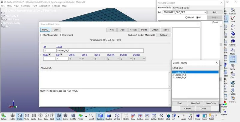 Figure9
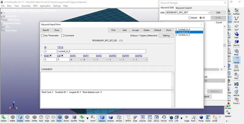
Figure10
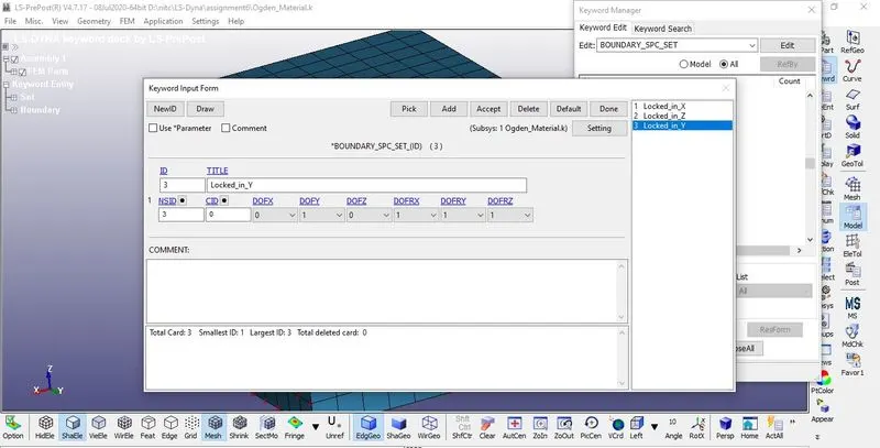
Figure11
6. Prescribed Motion:
A Set Of Nodes are created Along with the Face Of the Box opposite to the Fixed Face And Named As Displace
Nodes. Displacement is Given To the Node set Created Using Prescribed Motion Set By Boundary> Prescribed Motion set as shown in below Figure12.
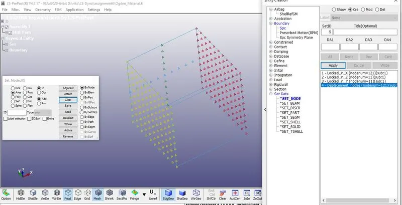 Figure12
The Load to be Applied On the Moving face to attain stretch Ratio is calculated
Stretch ratio I is defined as the ratio between the final length L and the initial length LO of a component i.e. it is equal to (1+ engineering strain)
Engineering Strain= `epsilon_{e} = (delta*L)/L`
`lambda = 5, L = 10`
`5 = 1 + (delta*L)/10`
`delta*L = 40mm`
For the safer Side, The Displacement is given as 50mm
A curve is defined with the Displacement of 50mm as shown in Figure13.
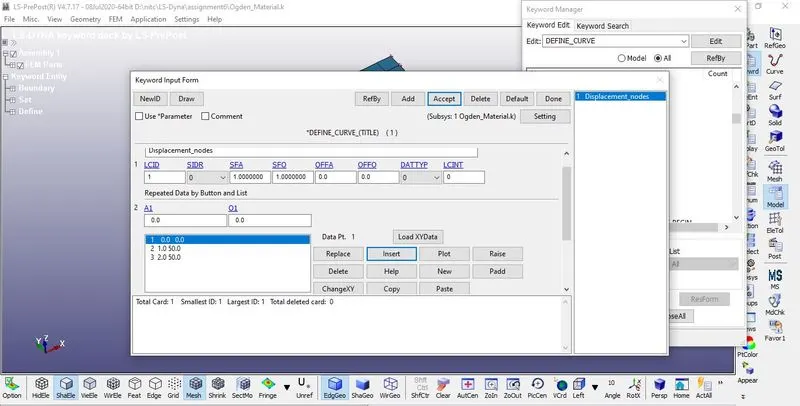 Figure13
The Displacement curve is assigned to the set of Displacement Nodes created as shown in Figure14.
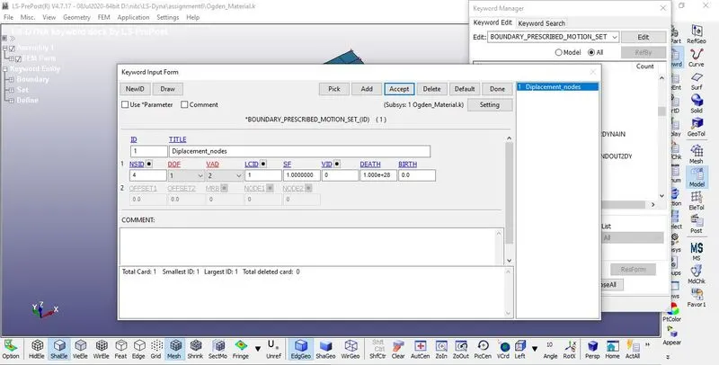
Figure14
As the Material, we use here is An Ogden model is a hyperelastic material model that can be used for predicting the nonlinear stress-strain behavior of material such as rubber or polymer. In the Implicit method, displacement loading is recommended rather than Force load to achieve a more stable load. So this Problem is Solved using Implicit
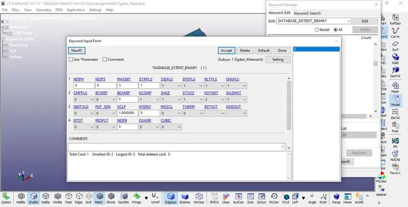
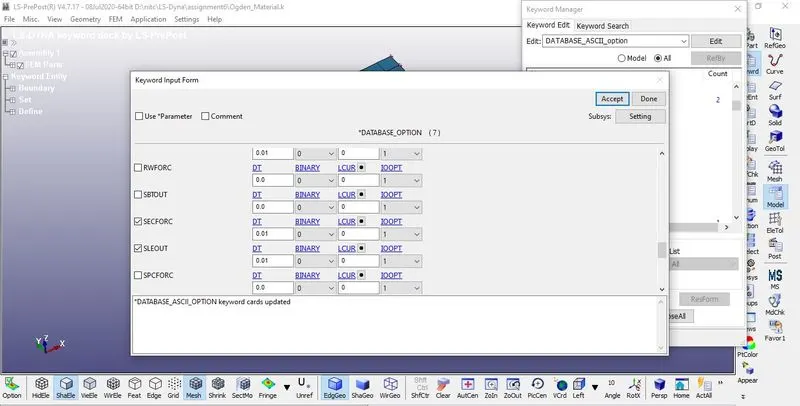
Create Implicit cards as shown in below Figures.
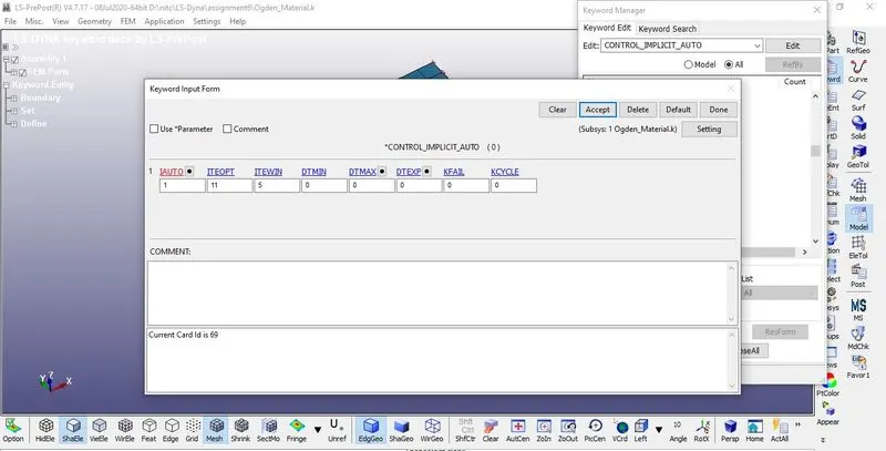
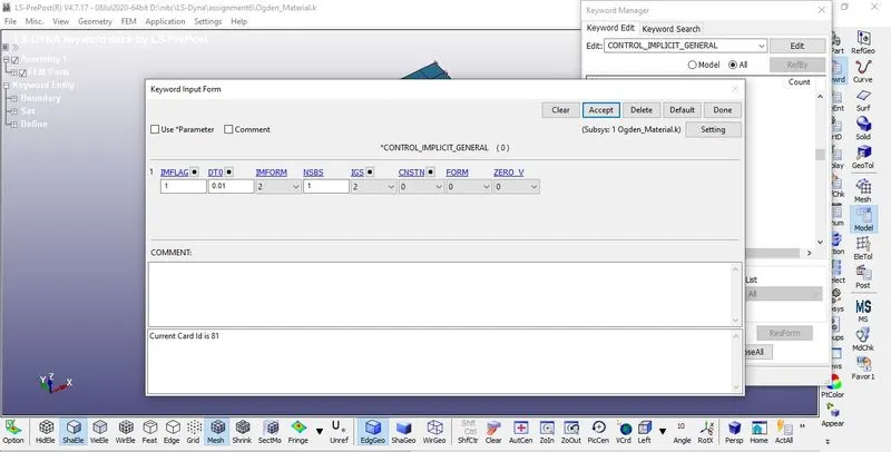
create output requests and control cards as shown in below Figures.
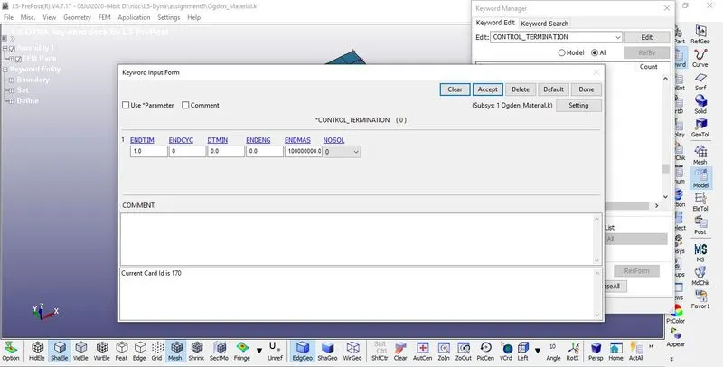
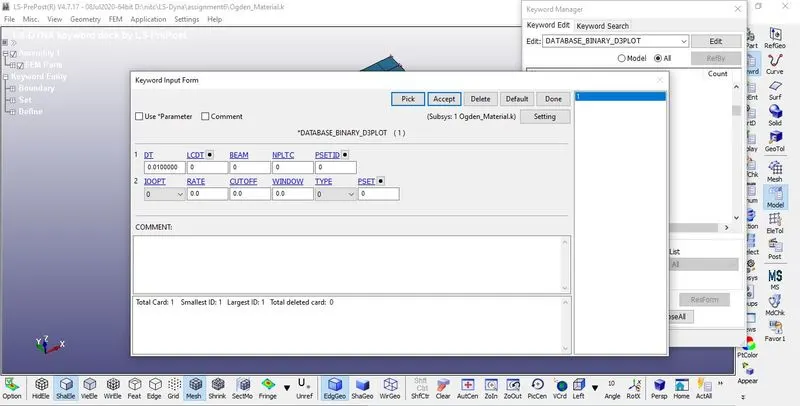
Model Checks:
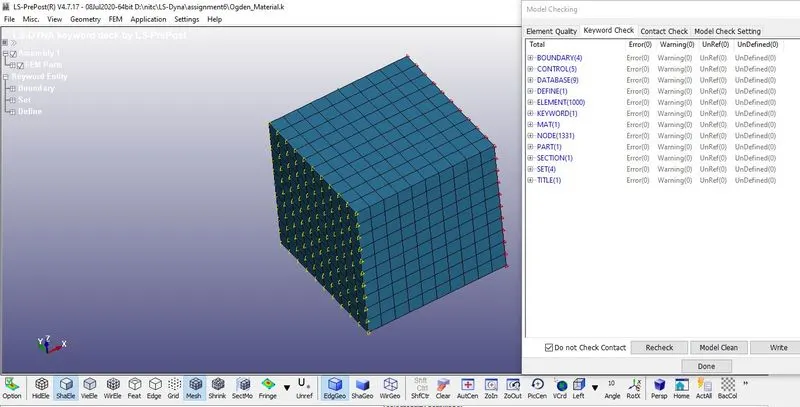
check the model whether any errors were there and correct them.
below figure shows the model after correcting the errors.
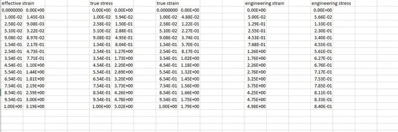
RESULTS:
element formulation1:
element formulation -1:
element formulation 2:
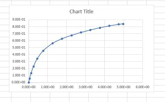
element formulation -2: