Week-6 Calculate the Stretch Ratio by comparing the ELFORM (-2,-1,1,2) with Ogden_Material Model.
OBJECTIVE: To create the 10*10*10 solid FE model and assign the ogden mat to and run a implicit analysis with different element formulations and compare the results.
PROCEDURE:
open the mat keyword file and create the FE model as box solid and assign the material to it and section as solid with element formaulation as '1' as shown below.
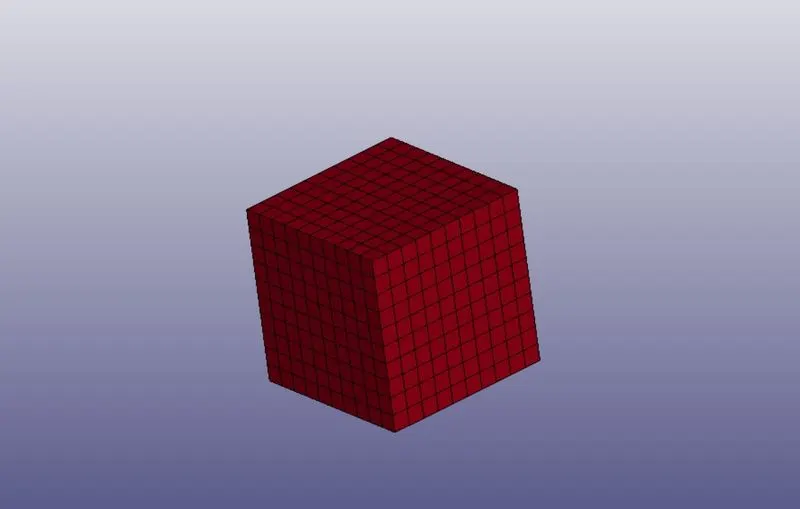
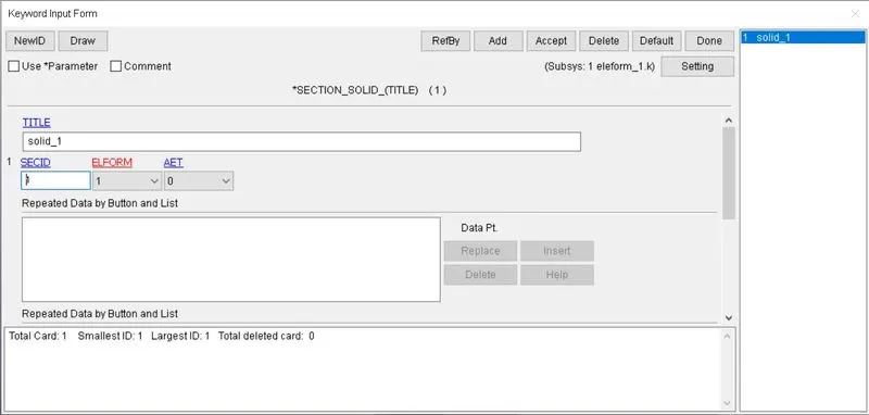
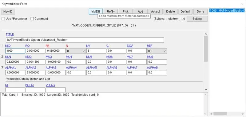
create boundary condition so that one end constrained in the z direction and constrained in the xy plane such that the square cross section shrinks equally along the edges.
create node sets as shown below.
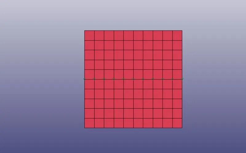
these nodes are along the X- axis so the it should have only one translational degree of freedom along the x axis.
create spc boundary condition by giving the DOFX as '0'.
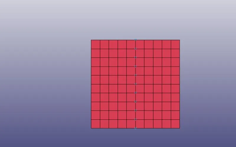
these nodes are along the y axis so we should allow only one translational degree of freedom along the Y axis.
create the spc set and put the DOFY as '0'
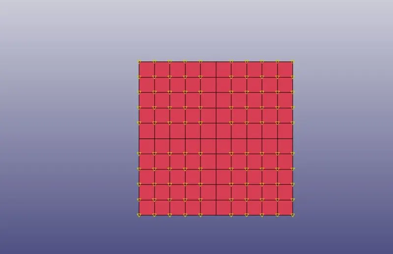
these nodes are free to move in the xy plane and so create the spc set and put the DOFX and DOFY as '0'
now the boundary condition of the stationary end is done.
now we have to give the load by defining the curve for displacement.
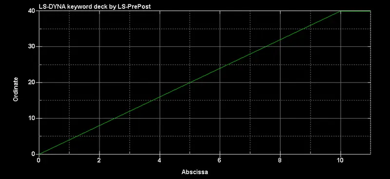
and then give prescribed motion set the for nodeset at the other end and set VAD option as 3 for assign the LCID.
as this is a quasi static problem we will use the implicit method to solve this.
for this we have to assign the implicit general card and IMFLAG as '1'
and give other implicit cards as shown below.
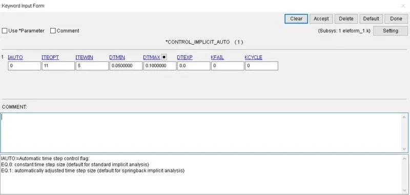
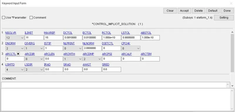
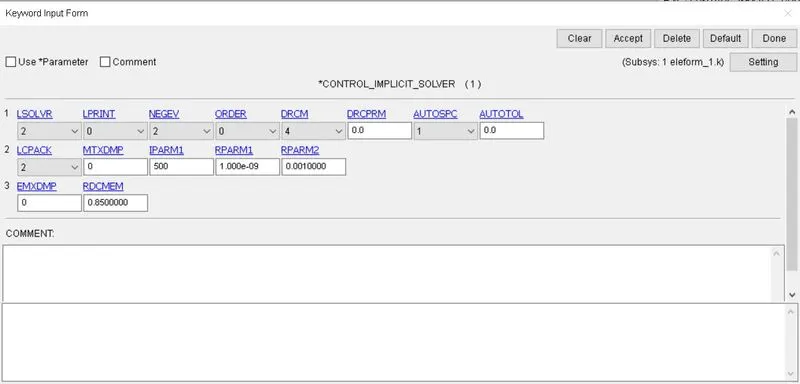
and give the termination card with termination time as 11 and give the general database ASCII and BINARY inputs and EXTENT_BINARY with STRFLG as '1'.
and run the simulation with this if it says normal termination run the same keyword with different element formulation for this challenge I used ELEFORM : 1, 2, -1, -2.
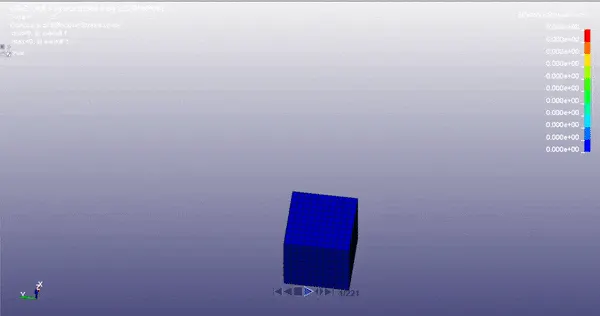
and the simulation is rendered as below.
using the history option I obtained the values for true stress and true stress in .csv file.
as the values are true stress and true strain, we have to convert them into engineering stress and strain.
true stress = engineering stress*(1 + engineering strain)
and true strain = ln(1 + engineering strain) `implies` (1 + engineering strain) = e^(true strain)`
and 1 + engineering strain = stretch ratio.
by converting the true stress and true strain into engineering stress and engineering strain.
I have plotted the graph of uniaxial stress vs stretch ratio.
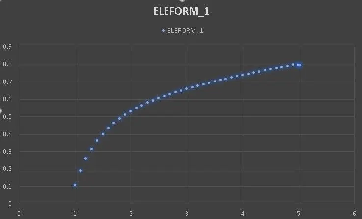
engineering stress on y-axis with units MPa vs stretch ratio of element formulation 1.
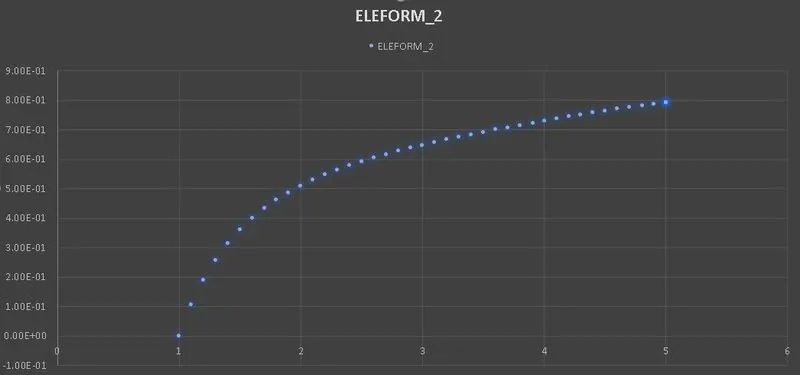
engineering stress on y-axis with units MPa vs stretch ratio of element formulation 2.
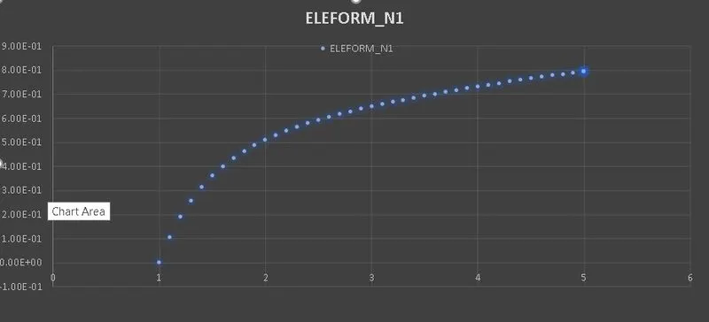
engineering stress on y-axis with units MPa vs stretch ratio of element formulation -1.
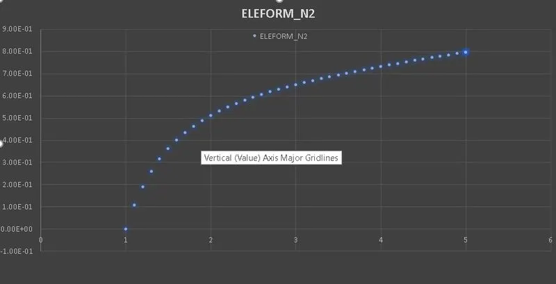
engineering stress on y-axis with units MPa vs stretch ratio of element formulation -2.
from above we can see that the curve are almost similar with little variations. as this is simple tensile behaviour the graphs are almost same. in case of complex problems like multi axial loading we can observe the visible variations between the element formulations.
CONCLUSION:
I understood how to run an implicit analysis and control cards of implicit domain. I have observed that the variations between element formulations and their results even though the differences are miniscule.