Week-6 Calculate the Stretch Ratio by comparing the ELFORM (-2,-1,1,2) with Ogden_Material Model.
WEEK 6 CHALLENGE - CALCULATE THE STRETCH RATIO BY COMPARING THE ELFORM (-2,-1,1,2) WITH OGDEN_MATERIAL MODEL
AIM:
To simulate tensile behavior by creating a Cube,use the material card attached (Ogden_Material.k). Applying appropriate boundary conditions to simulate tensile behavior for the model and finally compare the results from the simulation and plot the comparison of various ELFORMS against the Uniaxial Plot.Compare the results for the simulation using ELFORM = 1, 2, -1, -2
DELIVERABLES:
- An excel sheet with proper conversion and calculation of Stress/Strain and the Stretch Ratio for all the ELFORM.
- A proper image of the plot comparison of various ELFORMS against the Uniaxial Plot given in the challenge.
HINTS:
- LS-DYNA the output of stress and strains from Post FringeComp Stress/Strain is given as true stress and strains.
- Stretch ratio l is defined as the ratio between the final length L and the initial length L0 of a component i.e. it is equal to (1 + engineering strain)
- Your boundary condition should be relatable with the real-time boundary condition.
- You need to add *Database_Extend_Binary card and activate the STRFLG to get the strain data.
PROCEDURE:
Step 1: Open the Ogden material which is given in the .k format in the Ls-Dyna
MATERIAL CARD
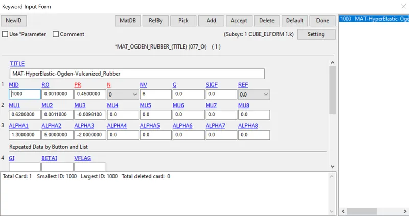
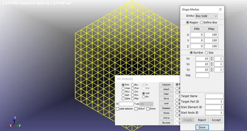
Step 2: We have the material card then we need to create a Cube. To create a cube Go to FEM_Element and Mesh_Shape Mesher and create the block mesher with a dimension 10mmx10mmx10mm and accept it.
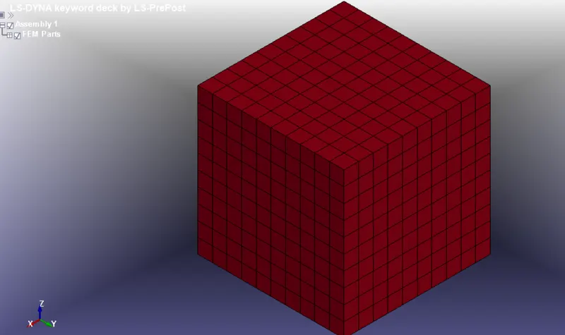
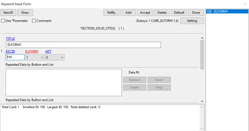
Step 3: Now we have the cube with mesh and material card which is given next we have to create a Section solid for the cube, Go to section and select Solid and give the Elform as 1.
ELFORM:=Element formulation options:
EQ.-2: fully integrated S/R solid intended for elements with poor aspect ratio, accurate formulation
EQ.-1: fully integrated S/R solid itended for elements with poor aspect ratio, efficient formulation
EQ.1: constant stress solid element (default)
EQ.2: fully integrated S/R solid
SECTION CARD
PART CARD
Assign the material and Section solid to the Cube part we have created.

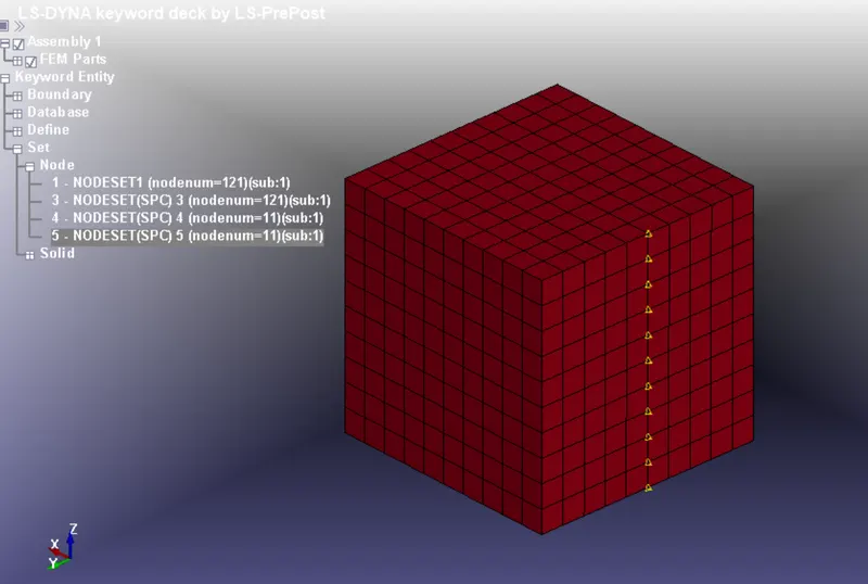
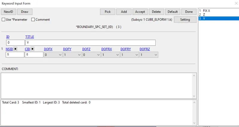
For tensile test we need to create a constraint and displacement for the cube.To create constraint, go to the create entity and select the boundary option and select the spc option with various constraints by arresting the axes.
BOUNDARY CARD
BOUNDARY SPC:
Nodes fixed in X direction and also rotation as shown below:
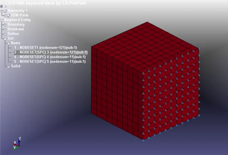
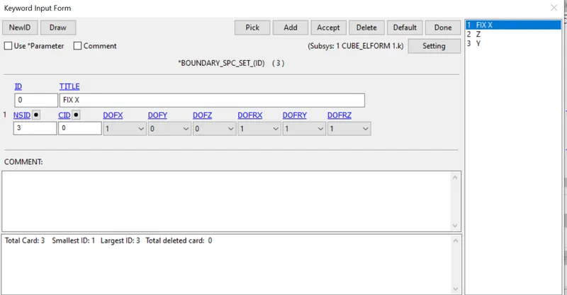
Nodes fixed Z direction in Y axis as shown below:
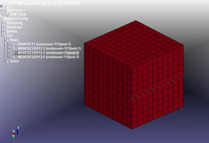
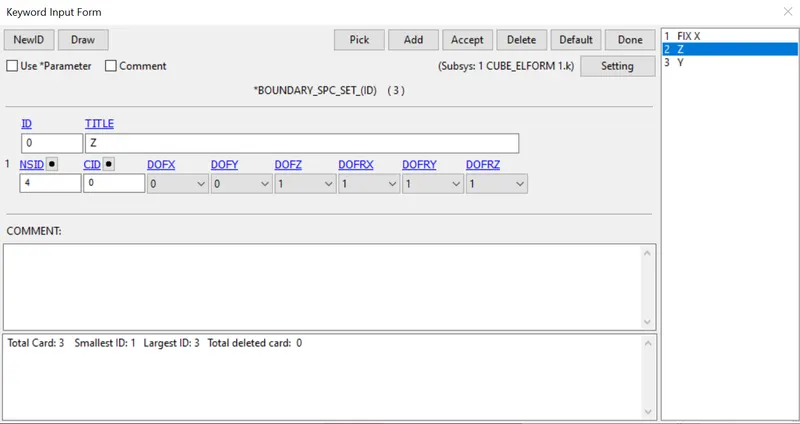
Nodes fixed in Y direction in Z axis as shown below:
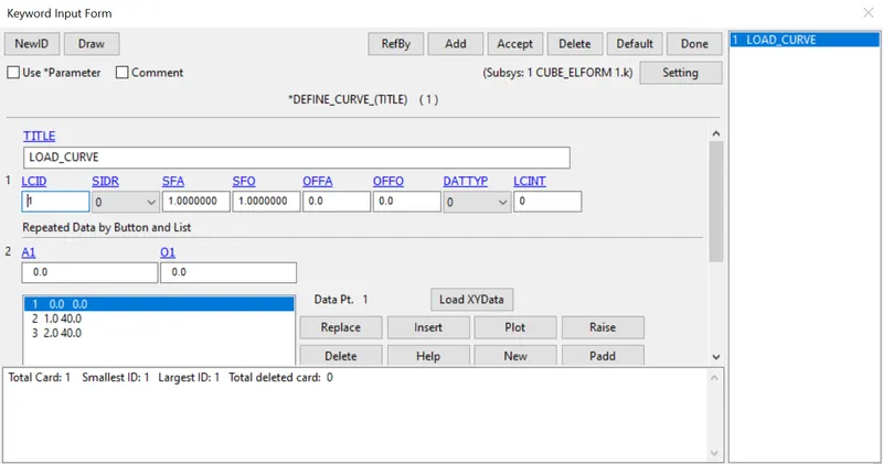
The minimum load to be applied on the moving surface to attain a stretch ratio of 5 is calculated by using following relation,
Engineering strain, εe = δL /L
Stretch ratio, λ = 1+εe
5 = 1+ δL /10
δL = 40 mm.
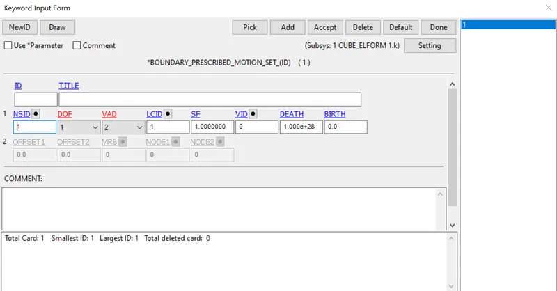
BOUNDARY_PRESCRIBED_MOTION_SET:
This card is used to apply the boundary condition on the moving surface
CONTROL CARD
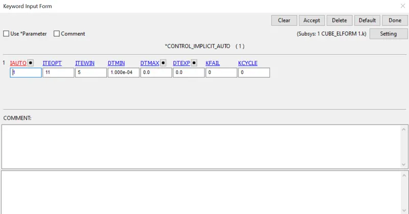
Control_Implicit_Auto card is used for automatic time step control during implicit analysis. IMFLAG= 1
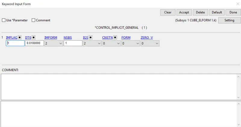
Control_Implicit_General card is used to activate implicit analysis and define associated control parameters.
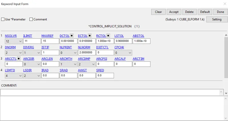
Control_Implicit_Solution card is used to specify whether it is a linear or non linear solution.
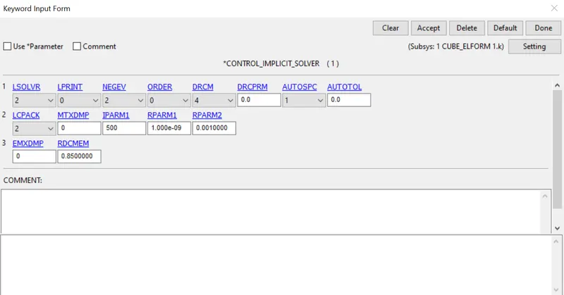
Control_Implicit_Solver card is used for Implicit Calculation.
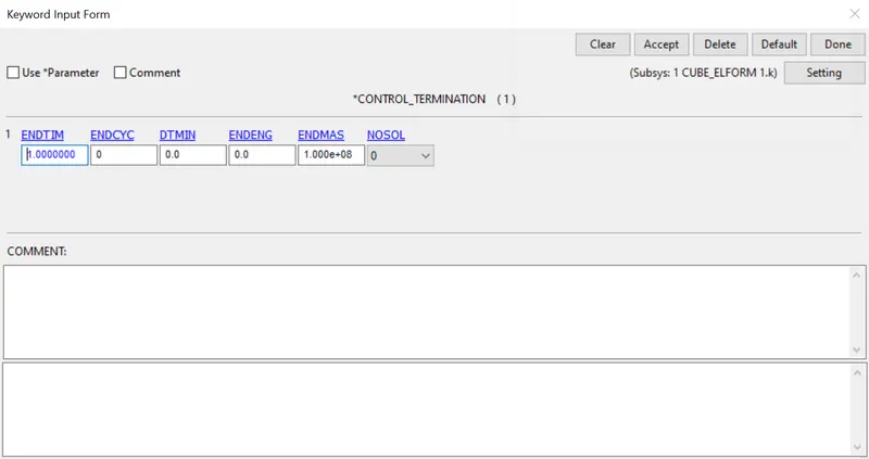
Control Termination:
This card is enabled to specify the end time of simulation,which is 1ms.
DATABASE CARD
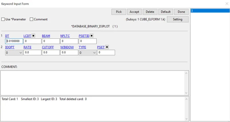
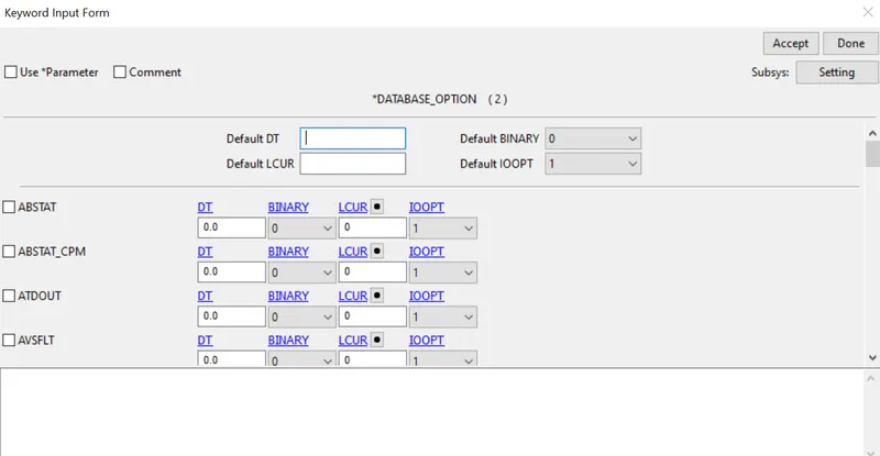
The time step value of 0.01ms is given for BINARY_D3PLOT and DATABASE_ASCII Option for GLSAT and ELOUT
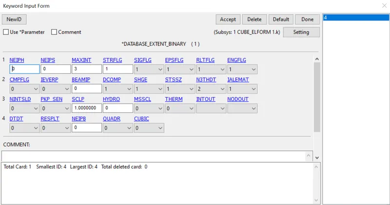
DATABASE_EXTENT_BINARY:
This card is used to compute the elastic Strain in the model
DATABASE_BINARY_D3PLOT:
ASCII OPTION:
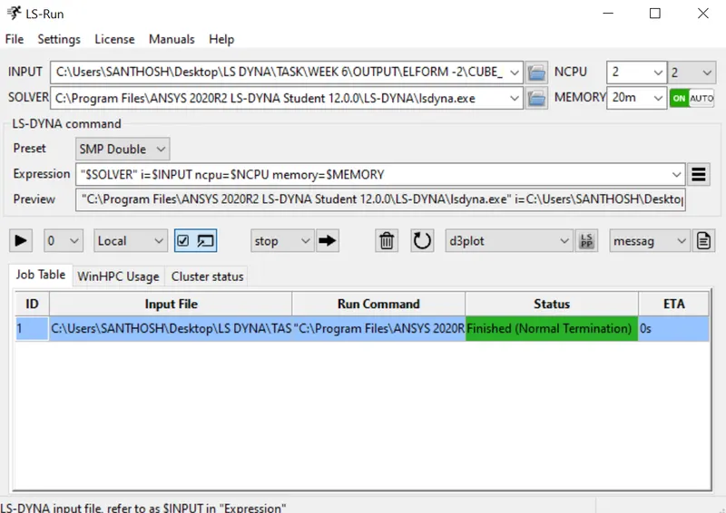
The model has been checked error and ready to run the simulation, file is saved as .k extension and it is run in LS Run by getting a normal termination for different cases of ELFORM.
Similary follow the case with different Value of ELFORM(-1,2,-2) with the same Model.
OUTPUT:
The D3plot result file is opened in Ls-Prepost by using option File_Open_LS-DYNA binary plot
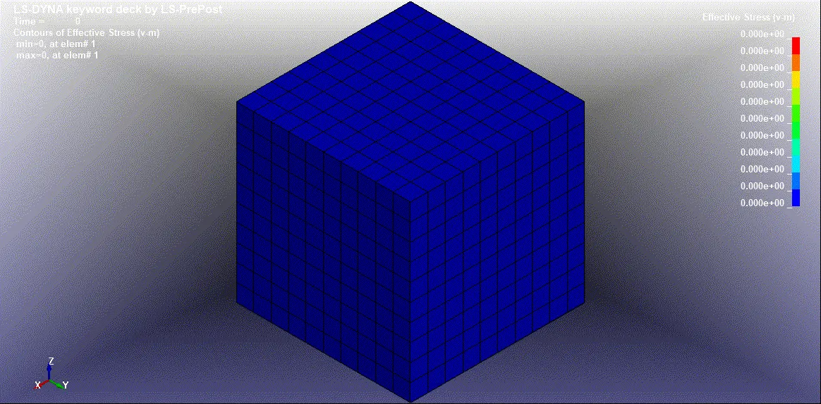
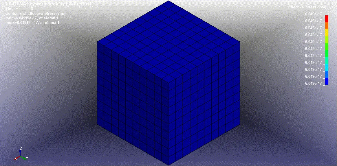
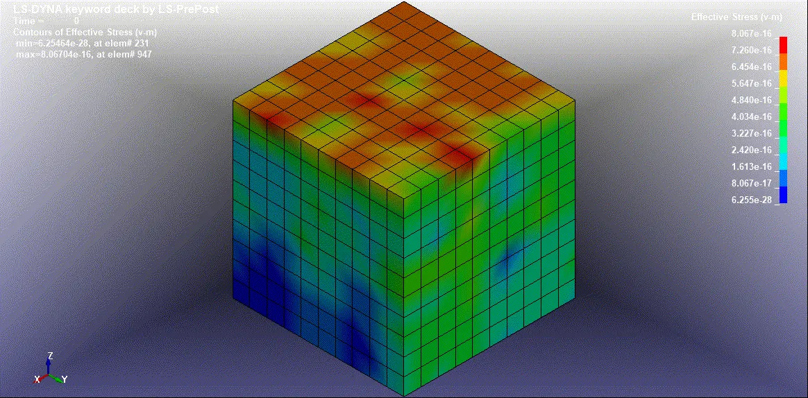
1. Animation of Von-Mises Stress Contour in Different Value of ELFORMs:
ELFORM 1:
ELFORM -1:
ELFORM 2:
ELFORM -2:
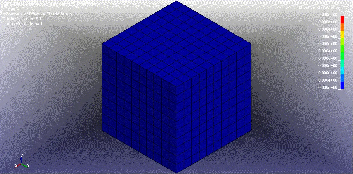
2. Animation of Effective plastic Strain Contour in Different Value of ELFORMs:
ELFORM 1:
ELFORM -1:
ELFORM 2:
ELFORM -2:
3. Calculation of Engineering Stress/Strain and Stretch Ratio:
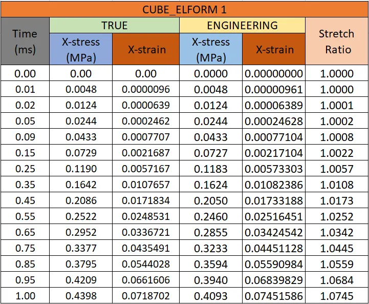
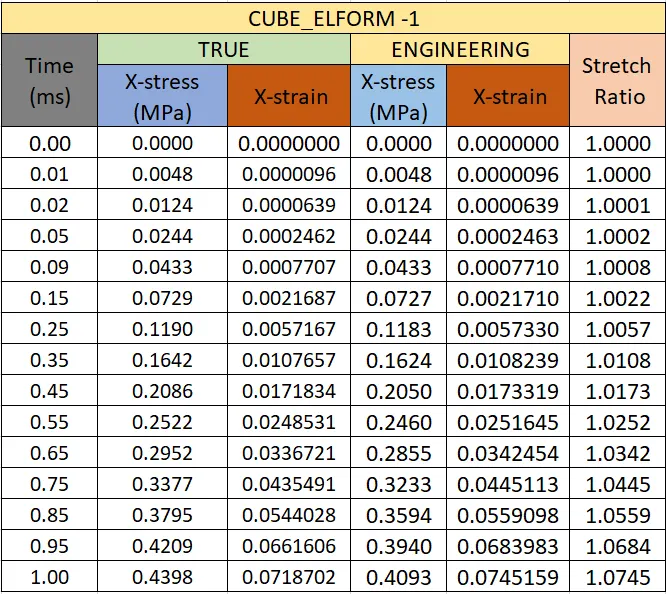
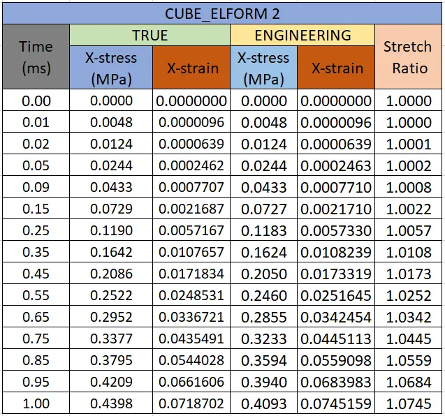
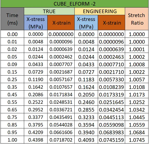
The output of Stress and strain from post Fringe Comp Stress/Strain is taken as true Stress and Strains.To find the Engineering Stress/Strain and Stretch Ratio are followed by below relations,
We know that True Stress,
σt = σe (1+εe)
Engineering Stress,
σe = σt / (1+εe)
Similarly, True strain,
εt = ln(1+ εe)
Engineering Strain,
εe = Exp (εt) -1
Stretch Ratio,
λ = 1+ εe
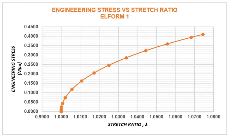
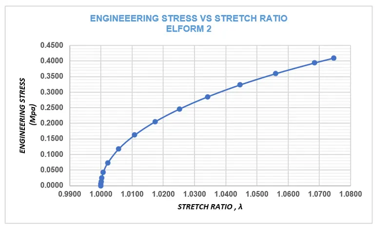
By following These equation we can calculate Engineering Stress/Strain and Stretch Ratio, Also Plot Graph for Engineering Stress vs Stretch Ratio as shown below;
(ELFORM 1) ENGINEEERING STRESS VS STRETCH RATIO:
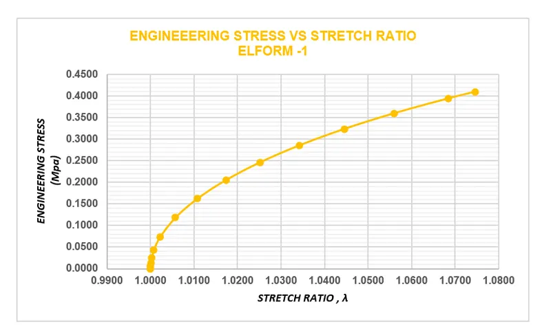
(ELFORM -1) ENGINEEERING STRESS VS STRETCH RATIO:
(ELFORM 2) ENGINEEERING STRESS VS STRETCH RATIO:
(ELFORM -2) ENGINEEERING STRESS VS STRETCH RATIO:
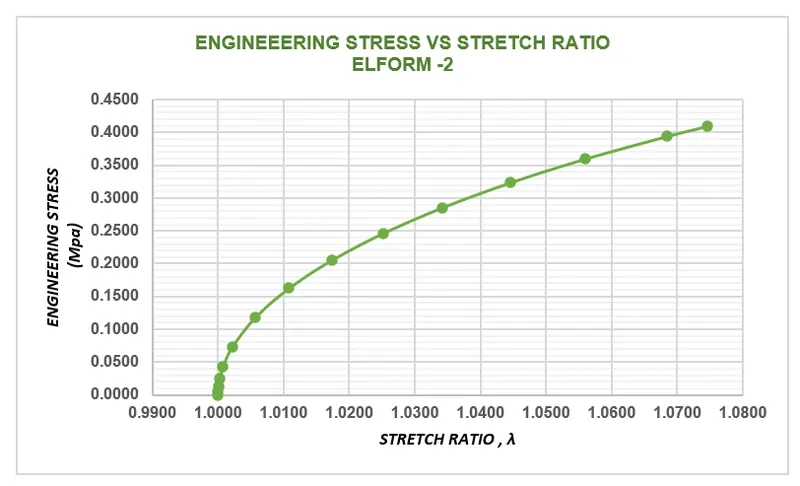
From the Graph plotted for Engg. stress vs Stretch ratio for Different cases, the output of ELFORM gives approximately same results since the model and loading Conditions are simply same.
CONCLUSION:
Thus we have done a simulation on the Ogden Material Cube with unaxial tensile load and find out the engineering Stress/Strain and Stretch Ratio and Alos plotted the Graph of Normal Stress vs Stretch Ratio.