Week-6 Calculate the Stretch Ratio by comparing the ELFORM (-2,-1,1,2) with Ogden_Material Model.
Objective :-
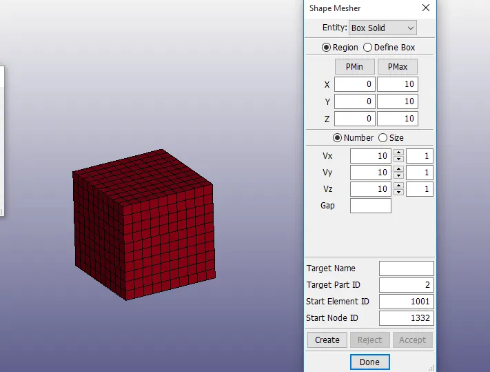
Create a block of 10mmx10mmx10mm dimension with 10 elements for each direction
Use appropriate boundary conditions to simulate tensile behavior for the model and finally compare the results from your simulation to the plot above up to stretch ratio 5. Only the uniaxial plot is to be compared.
Compare the results for the simulation using ELFORM = 1, 2, -1, -2
Use a proper solver (Implicit/Explicit) and also explain the reason.
Procedure :-
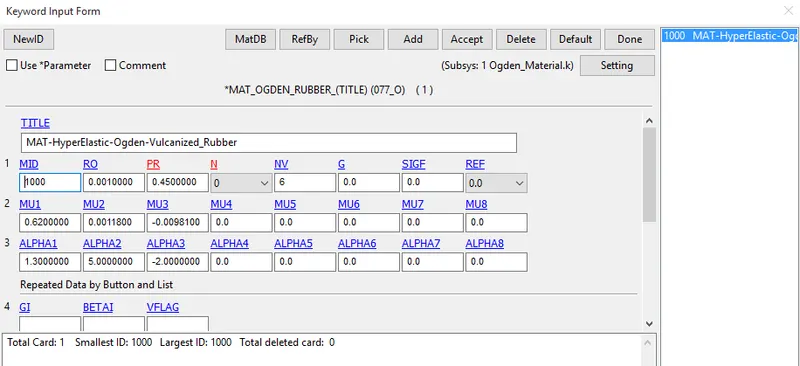
- Open the given keyword file (ogdan_material.k)
- The imported file consist of ogdan material card only
- Created a block of 10mmx10mmx10mm dimension with 10 elements for each direction using shape mesher option
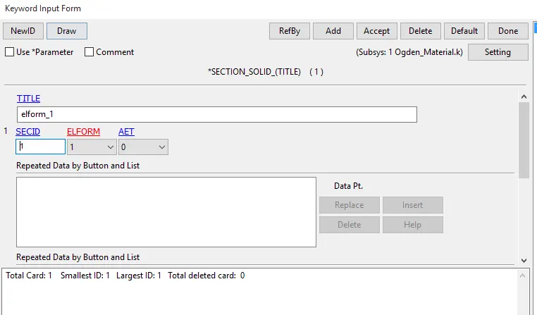
Section
- Case -1 To create section, go to Section - solid put Elform as 1
- Elform 1 means constant stress solid element (default)
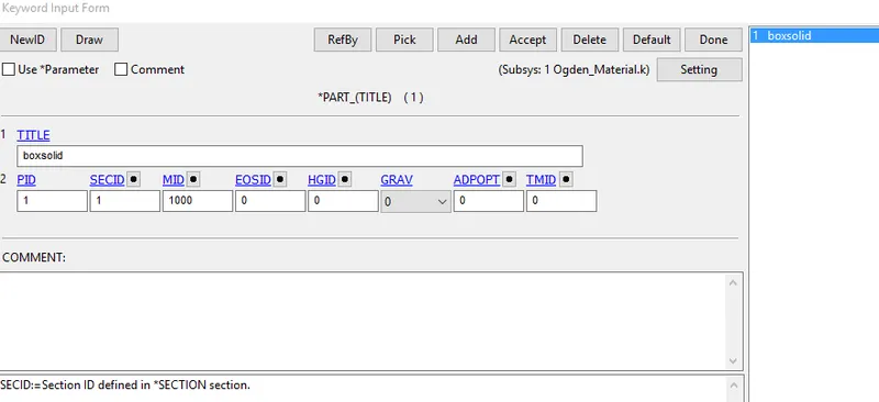
Part
Assign the given material card (ogdan material) and created section card (Elform 1) to the part.
Boundary conditions
- To Perform uniaxial tensile test on the specimen, the nodes on one of the faces are fixed along the X-axis
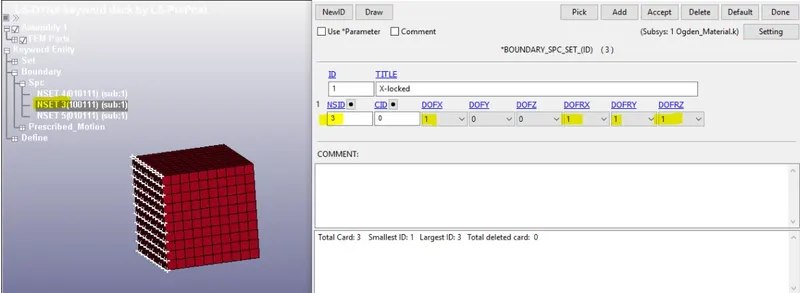
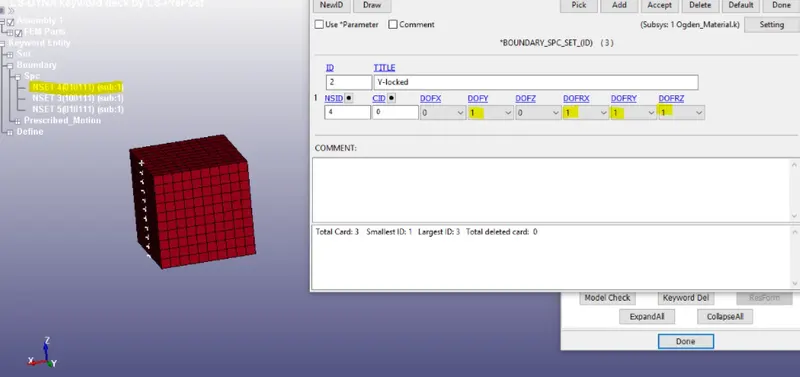
- Constrained in Y-axis
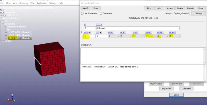
- Constrained in Z-axis
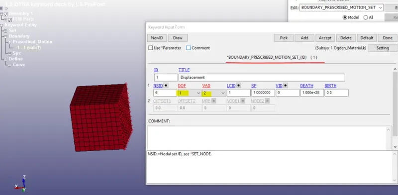
- Selected node set for applying displacement load
Load curve
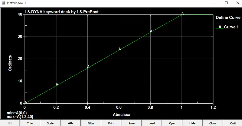
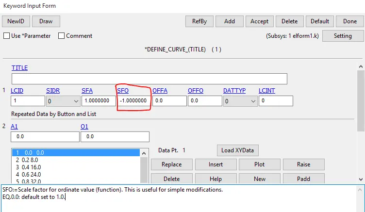
- The minimum load applied on the moving face will be calculated by using the following relation.
True strain = ln (1 + engineering strain)
Stretch ratio = 1 + engineering strain
Stretch ratio is defined as the ratio between the final length L and the initial length L0 of a component
given data
Stretch ratio = 5
initial length L0 = 10
Substitute given values in equation
Stretch ratio = 1 + engineering strain
5 = 1+ δ L /L
δ L = 40mm.
Control cards
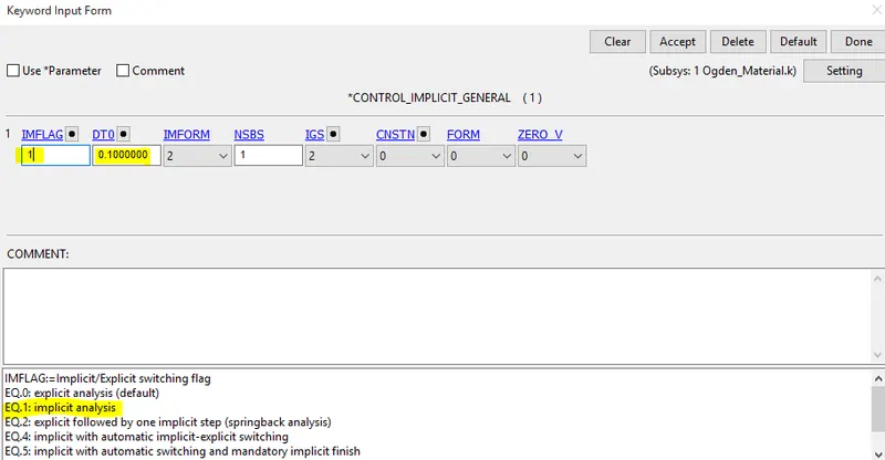
*CONTROL_IMPLICIT_GENERAL - activates implicit analysis
DT0 =Initial time step size for implicit analysis = 0.1
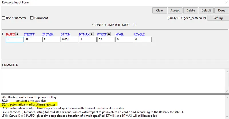
*CONTROL_IMPLICIT_AUTO card
DTMAX = Maximum allowable time step size (default = DT*10)
DTMIN = Minimum allowable time step size (default = DT/100).
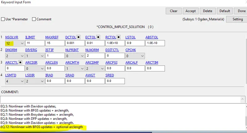
*CONTROL_IMPLICIT_SOLUTION
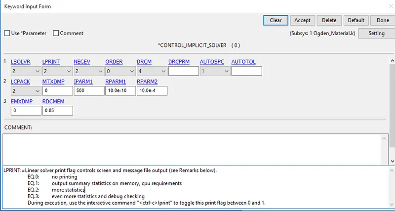
*CONTROL_IMPLICIT_SOLVER
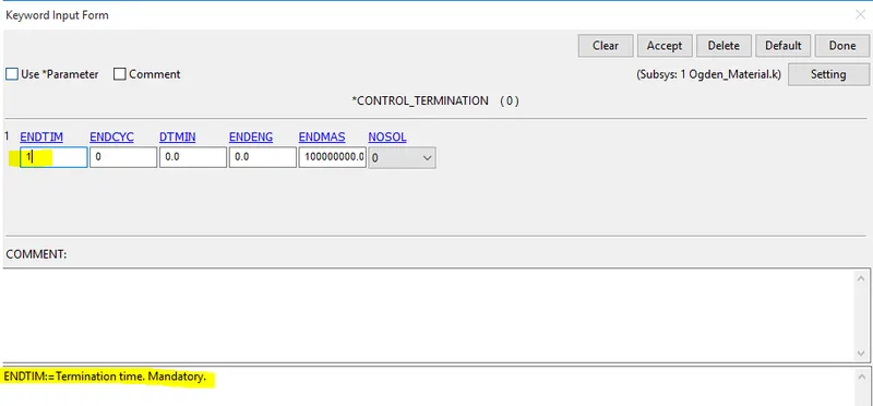
*CONTROL_TERMINATION
Database
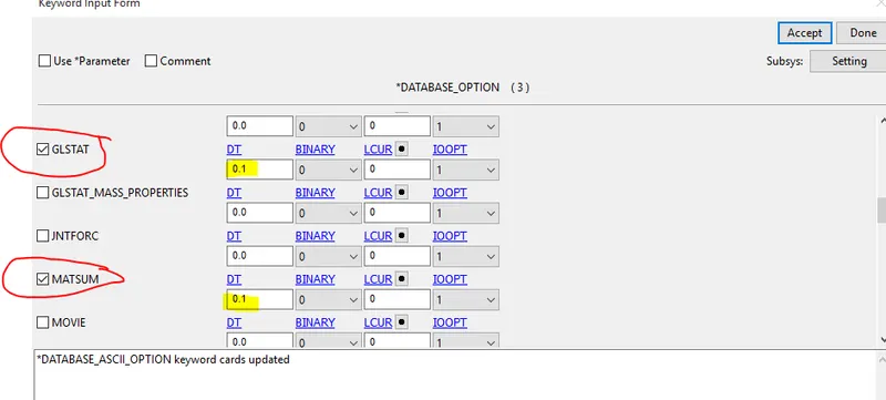
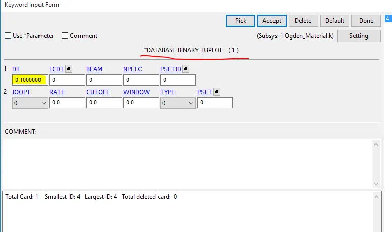
- Create Database card for ASCII file and select glstat, matsum,elout and nodout with DT 0.1 and Binary d3plot with DT 0.1
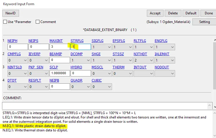
- To get directional strain, create a database card for extent_binary with STRFLG value as 1
- save the keyword file with an extension of .k
Follow the same procedure for remaining cases also
Case -2 :
- Elform 2 means fully integrated S/R solid
Case -3 :
- Elform -1 means fully integrated S/R solid intended for elements with poor aspect ratio, efficient formulation.
Case -3 :
- Elform -2 means fully integrated S/R solid intended for elements with poor aspect ratio, accurate formulation.
Simulation
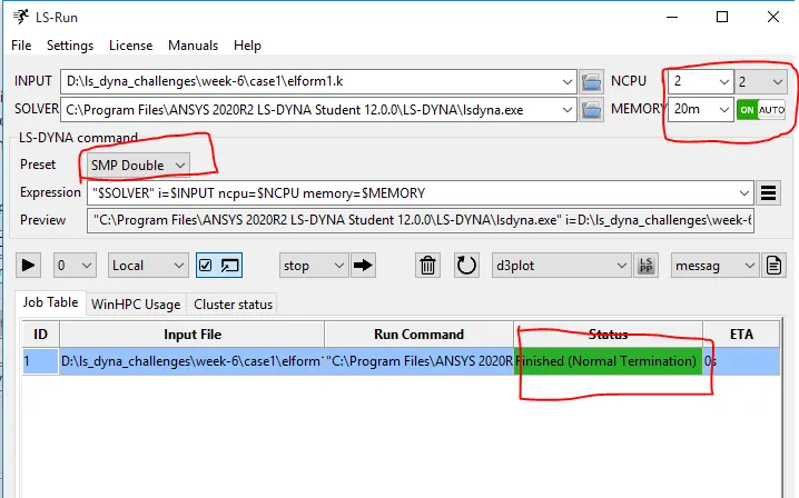
no.of. cpu = 2
memory = 20m = 800mb (1m = 40mb)
solver = double precision solver
Results
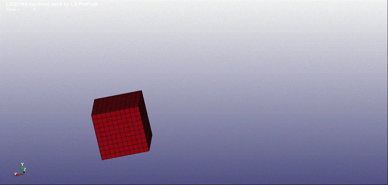
Animation of component
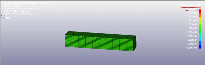
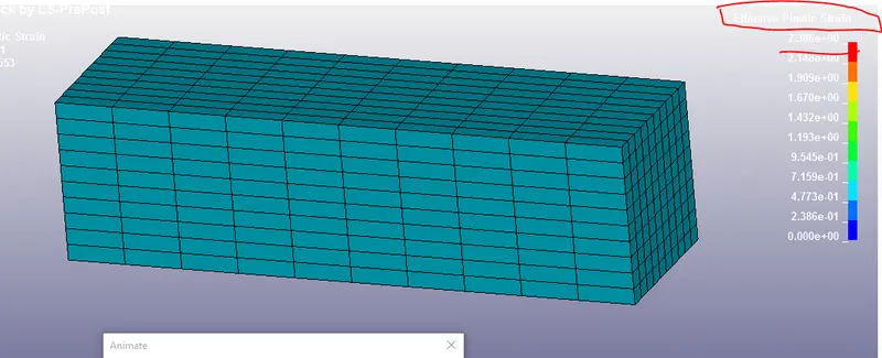
case 1:- Von misses Stress and Effective plastic strain (elform 1)
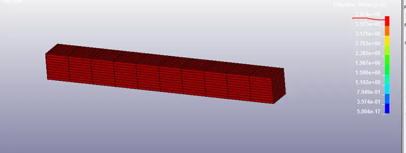
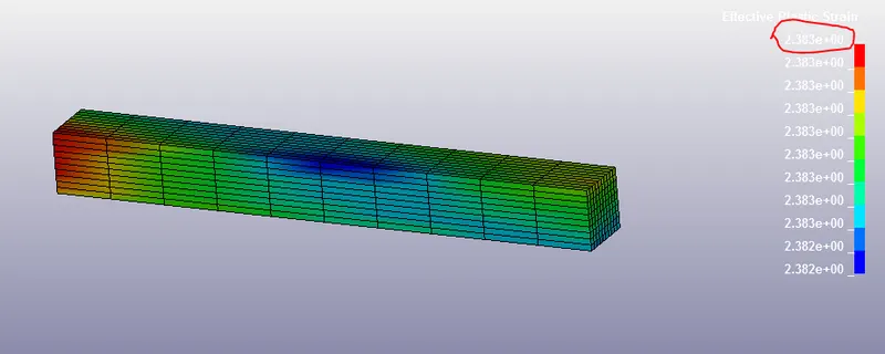
case 2:- Von misses Stress and Effective plastic strain (elform 2)
case 3:- Von misses Stress and Effective plastic strain (elform -1)
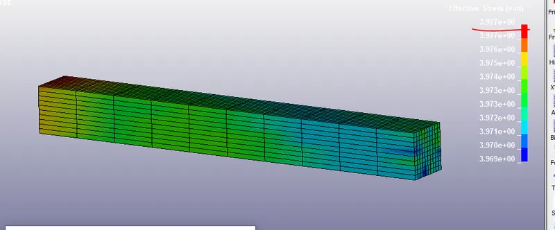
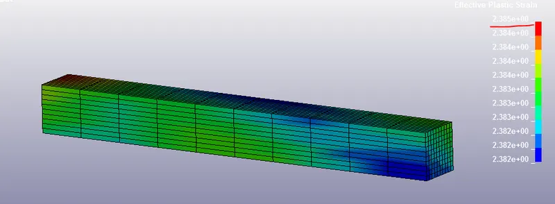
case 4:- Von misses Stress and Effective plastic strain (elform -2)
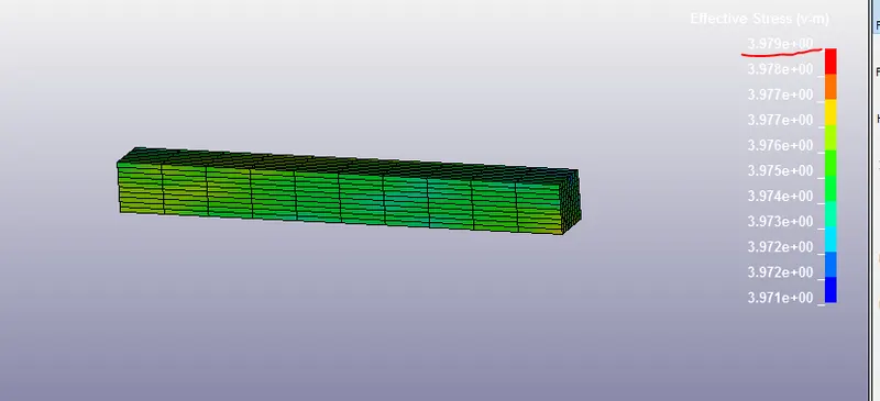
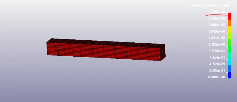 `lamda`
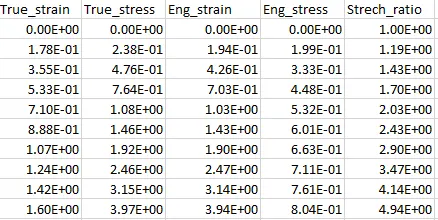
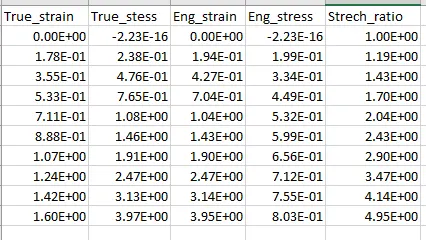
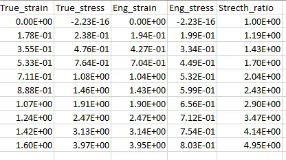
Calculation of Engineering_strain, Engineering_stress and Stress_ratio.
- LS-dyna generates True stress & True strain values, To find Engineering_strain, Engineering_stress and Stress_ratio Following relations are used.
- σt = σe (1+Ee)
- Et = ln (1+Ee)
- λ = (1+Ee)
Where
σt = true_stress
σe = engineering_stress
Ee = engineering_strain
Et = true_strain
λ = Strech_ratio
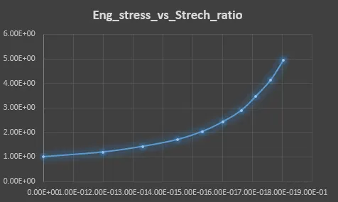
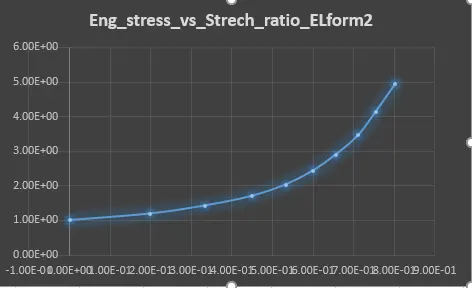
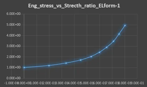
- calculated Engineering_strain, Engineering_stress and Stress_ratio using above relations with the help of excell sheet, results pictures are attached below.
case1
case2
case3
case4
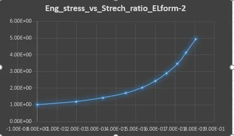
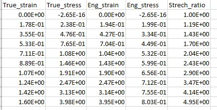
CONCLUSION
- From the above graphs, we can observe that results are same for different ELFORM (1,2,-1,-2)
- The uniaxial tension test was solved using an implicit solver, since the analysis is similar to quasi-static analysis on hyperelastic non-linear matrial with slow steady loading conditions.