Week-6 Calculate the Stretch Ratio by comparing the ELFORM (-2,-1,1,2) with Ogden_Material Model.
Odgen Material Model
Objective
To simulate a tensile test on a 10x10x10mm cube using the given Ogden material card and compare the difference in using Elform 1,-1,2 and -2 property.
Condition
- Stretch Ratio of at least 5 should be achieved
- The units system to be used is gm-mm-ms
Deliverables:
Deliverables:
- An excel sheet with proper conversion and calculation of Stress/Strain and the Stretch Ratio for all the ELFORM.
- A proper image of the plot comparison of various ELFORMS against the Uniaxial Plot given in the challenge.
Theory
Rubber is generally considered to be fully incompressible since the bulk modulus greatly exceeds the shear modulus in magnitude. To model the rubber as an unconstrained material a hydrostatic work term is included in the strain energy functional which is a function of the relative volume, 𝐽, [Ogden 1984]
𝑊∗ =∑∑𝜇𝑗 𝛼𝑗 𝑛 𝑗=1 3 𝑖=1 (𝜆𝑖 ∗𝛼𝑗 − 1) + 𝐾(𝐽 − 1 − ln𝐽)
The stress/strain values obtained from ls Dyna are the true stress/strain values
To plot the nominal stress vs stretch ratio it is necessary to convert them to engineering stress/strain respectively.
Note: Stretch Ratio=1+Engineerying Strain.
True strain = ln(1 + engineering strain) where ln designates the natural log
True stress = (engineering stress) * exp(true strain) = (engineering stress) * (1 + engineering strain) where exp(true strain) is 2.71 raised to the power of (true strain).
Solid Element Formulation
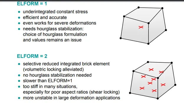
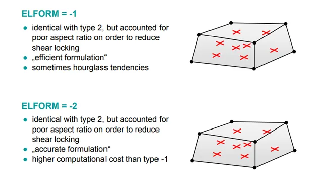
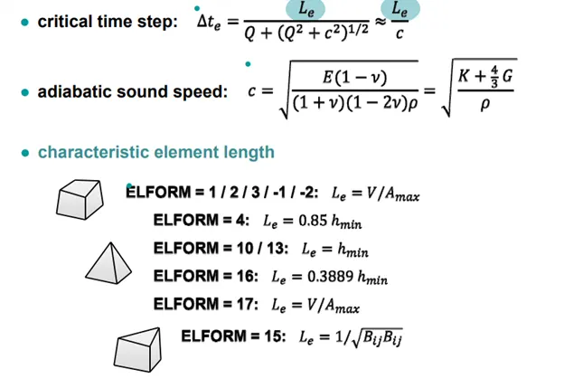
Procedure
- After Importing the keyword file, we can start by creating the 10x10x10mm cube
- In mesh, use the shape mesher to create the cube
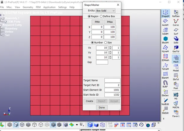
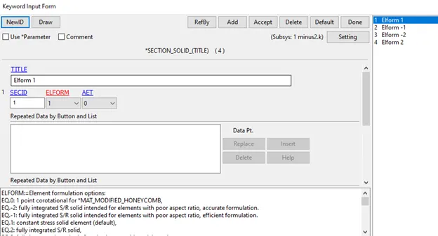
- Create solid section id for 4 the different element formulation.
Define the Load Curve
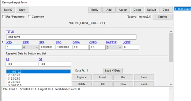
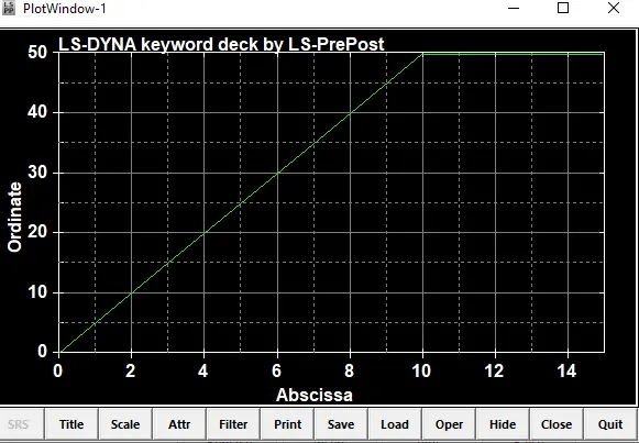
- In keyword manager, go to define curve and plot the values appropriately for a linear increase.
- Stretch Ratio= 1+engineering strain
- Considering that We need a stretch ratio of at least 5,
- 5=1+engstrain
- 4=Final Length/initial Length
- 4*10=final length
which gives us a value of 40mm as the final length - Just to be safe, we can define the curve for 50mm displacement.
Boundary Conditions
- Set the final layer of nodes on one side of the cube as rigid on the x-axis.
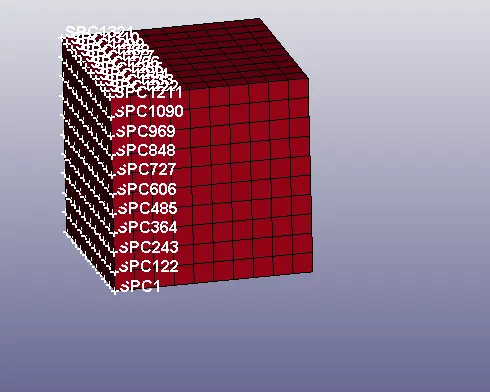
- For better stability, set a layer of nodes rigid on the normal axis.
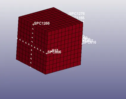
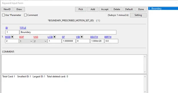
- After this, create a prescribed motion set for displacement. Set only the last layer of nodes opposite to the rigid ones for the Node Set Id.
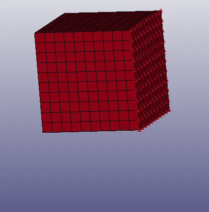
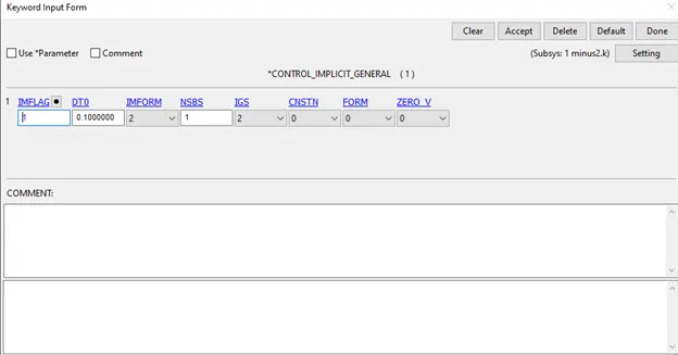
- Since the loading can be considered as Quasi-Static , an implicit solver can be chosen for this simulation and as such, implicit control keycards need to be created.
- It is recommended to go with the default properties for now
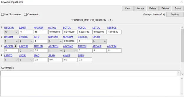
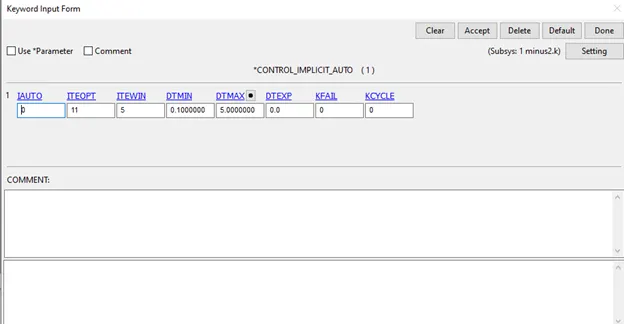
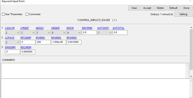
Output Files
- In database, create the d3plot, extent binary and Ascii keywords
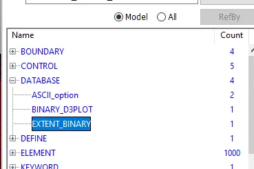
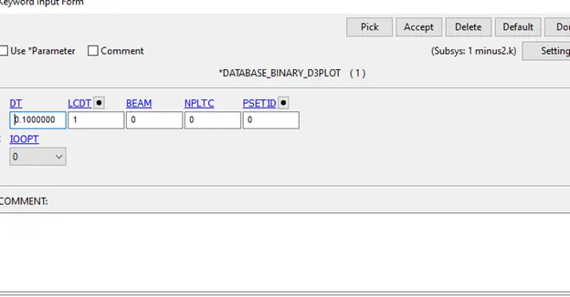
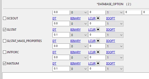
- In Ascii, enable Glstat and Matsum.
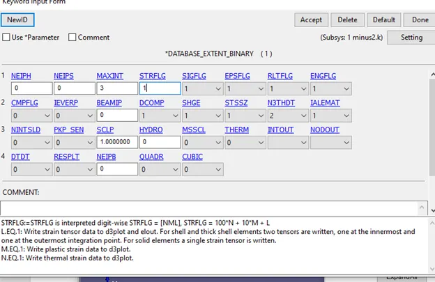
In extent Binary, set the values appropriately.
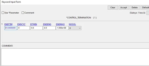
Control
- Create a Control Termination Keyword
Check the keywords using the model checker for errors
No errors only warnings unref sections, used for the different cases.
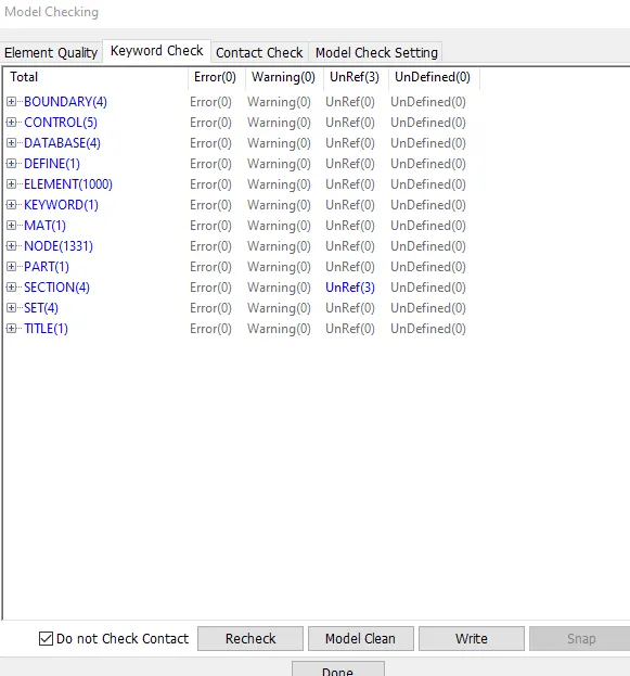
After this run the simulation using the ls Dyna solver
Make sure that the folder has no spaces and the termination is normal termination.
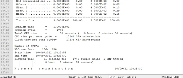
Post Processing
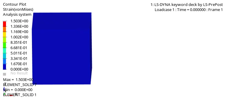
Since we are using a hyperelastic material there is no observable failure of elements during the simulation.
Elform1
To get true stress and true strain values, in post go to history->element and plot X stress and Ipt Lower x strain.
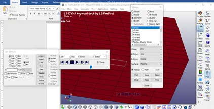
After plotting, save the plot interpolating 20 points for the graph.
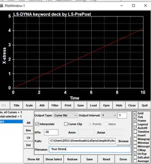
Save the file in different folders for each case for simplicity.
Do the same for true strain.
Open the files using notepad++.
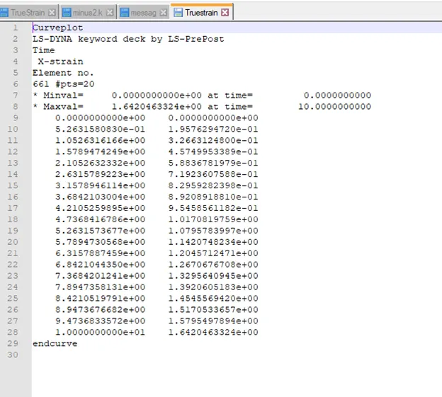
Plot them using excel.
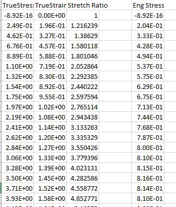
Do the same for the other 3 cases as well.
Plot the Eng Stress vs Stretch Ratio graphs for each case, either in the same chart or different ones.
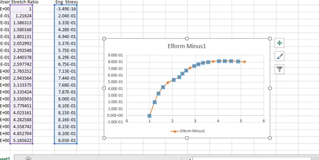
After plotting them, it can be observed that there is no discernable difference in the 4 cases.
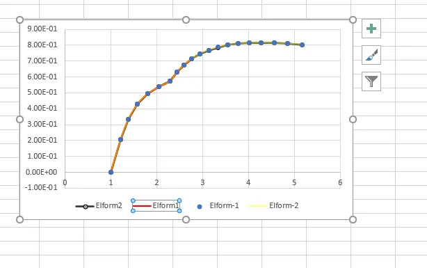
This indicates that the effect of Elform on Stress/strain is negligible due to the simple nature of the test.
Learning Outcomes
- Implicit Analysis in Ls Dyna
- Stretch Ratio vs stress graph
- Implicit Control Keywords
Conclusion
Element Formulation is an extremely important aspect of modelling a Fea simulation. Different types of Element formulation serve different purposes such as preventing shear locking of elements or reducing hourglass tendencies.
In this project, we modelled a simple tensile behaviour test on a cube using the given Odgen material model.After using differen Elform Types, it can be observed that the difference in the stress vs stretch ratio curves is negligible due to the simple nature of the test.