Week-6 Calculate the Stretch Ratio by comparing the ELFORM (-2,-1,1,2) with Ogden_Material Model.
AIM: Create a block of 10mmx10mmx10mm dimension with 10 elements for each direction and use the material card attached (Ogden_Material.k) that is representative of the material properties.Use appropriate boundary conditions to simulate tensile behavior for the model and finally compare the results from your simulation to the plot above up to stretch ratio 5 and Compare the results for the simulation using ELFORM = 1, 2, -1, -2, By using a proper solver (Implicit/Explicit).
Procedure:
1.Creating the Solid Cube
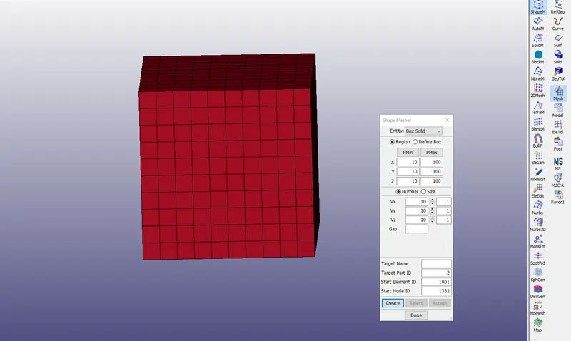
- Create a block of 10mmx10mmx10mm dimension with 10 elements for each direction
- Mesh>Shape Mesher and select as entity as solid and set xyz as 10mm and create the solid section Box.
2.Section:
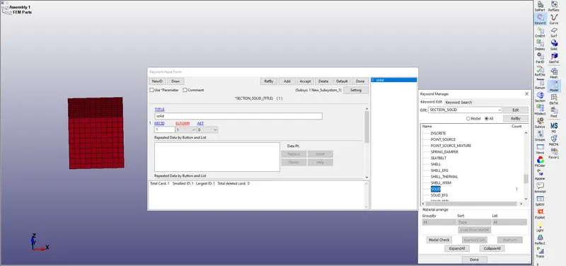
- For defining section to the solid block go to Keyword manager > All > Section > shell
- In this solid section we change the different Element formulations according to solve the problem, we have to use the different Element formulations such as (1, -1, 2, -2) for an individual purpose.
- EQ.1: constant stress solid element (default),
- EQ.-1: fully integrated S/R solid intended for elements with poor aspect ratio, efficient formulation.
- EQ.2: fully integrated S/R solid,
- EQ.-2: fully integrated S/R solid intended for elements with poor aspect ratio, accurate formulation.
3.Material:
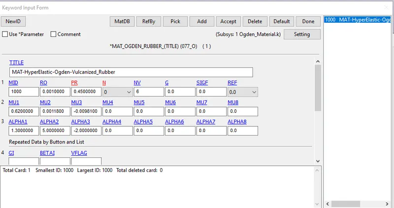
Here we use the default odgen material as mentioned.
4.Part:
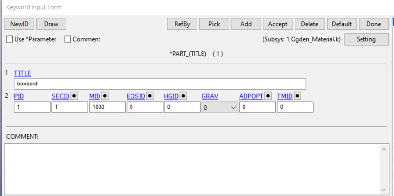
In this we basically assign the Material and Section to the part.
5.Boundary Conditions:
- Single Point Constraint Node(SPC):
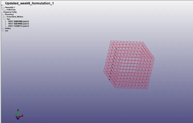
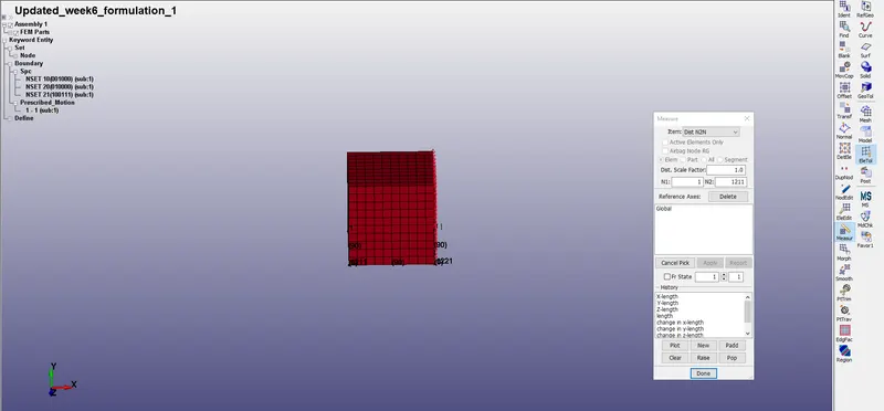
- In order to perform the tensile behaviour for the solid model in a Uni axial direction here we need to apply the boundary conditions on the cube.
- we need to consider the compression in other lateral directions that is decreasing the width of the box with an increasing the longitudinal length of the model with an application on single direction only.
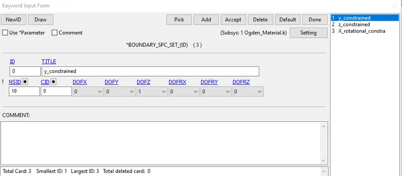
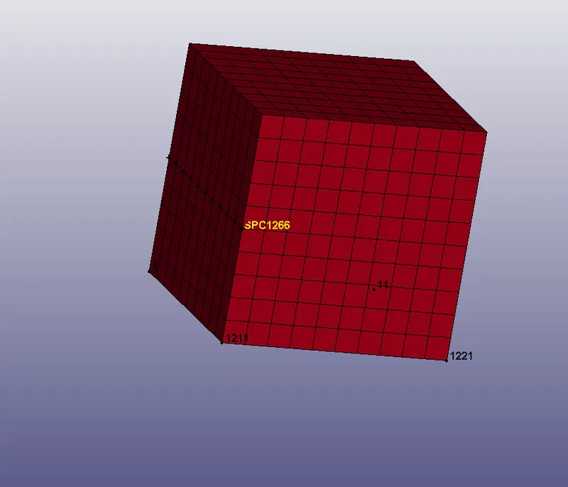
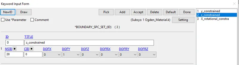
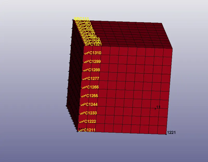
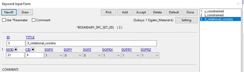
- So here we are applying the Boundary_Spc_Sets in such a way that the middle nodes and remaining nodes along the all directions are constrained.
Model> Create entity> Boundary> SPC> Apply.
In this we constrained the mid nodes in vertical direction and allow the x y dof and constrained in the Z direction.
2. Perscribed Motion Set:
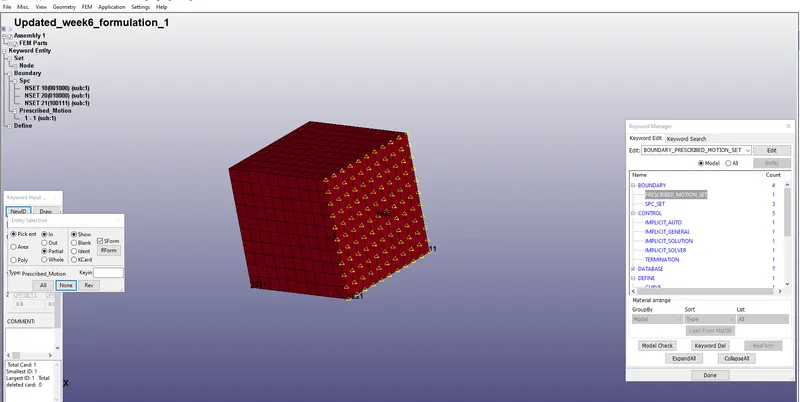
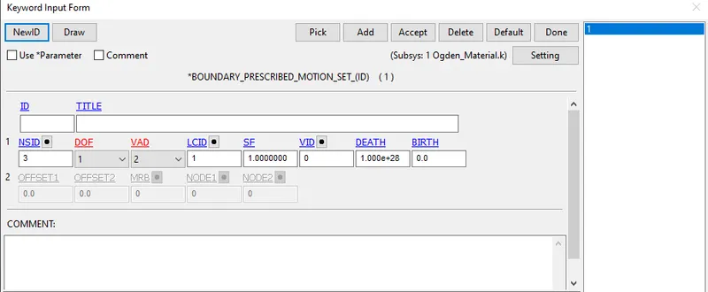
- A Set of Displacement nodes are created to the face of the solid Box in X_direction for representing a Tensile Behaviour.
- Edit the remaining parameters as VAD(EQ.2: displacement(rigid bodies and nodes), Load curve, scale factor.
As we know that Stretch Ratio:
`lamda=1+e`
where lamda =stretch ratio
e(engineering strain)=change in length/original length
lamda=1+dL/L
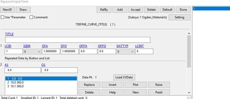
5=1+dL/90
4*90=dL
dL=360
6.Define_Curve:
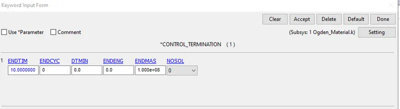
7.Control
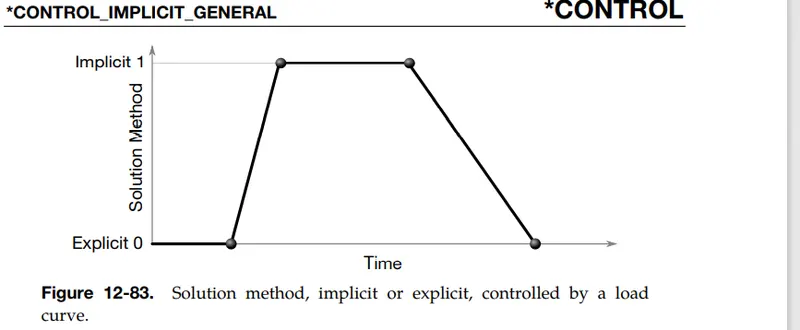
Implicit General:
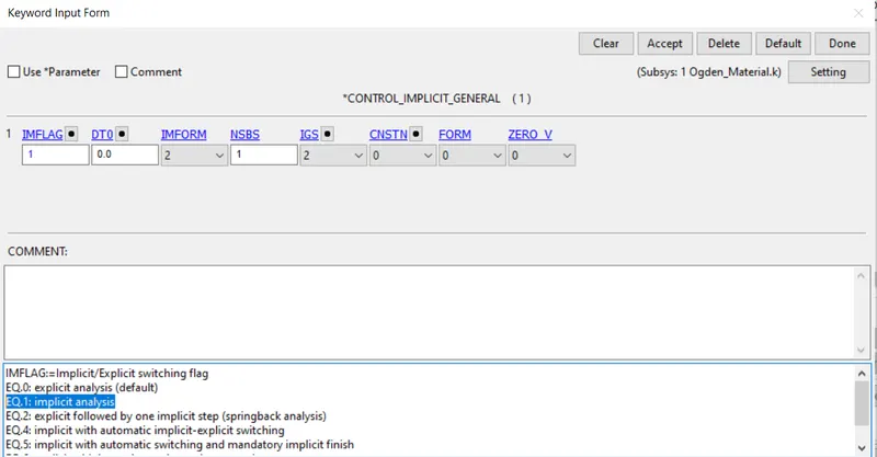
- Activate implicit analysis and define associated control parameters. This
keyword is required for all implicit analyses. - IMFLAG Implicit/Explicit analysis type flag (see Remark 1):
EQ.0: explicit analysis
EQ.1: implicit analysis
EQ.2: explicit followed by implicit, (seamless springback). *INTERFACE_SPRINGBACK_SEAMLESS is required to
activate seamless springback.
EQ.4: implicit with automatic implicit-explicit switching
EQ.5: implicit with automatic switching and mandatory
implicit finish
EQ.6: explicit with intermittent eigenvalue extraction
LT.0: curve ID = -IMFLAG specifies IMFLAG as a function of
time.
Implicit Auto:
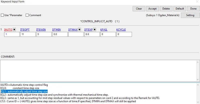
IAUTO Automatic time step control flag
EQ.0: constant time step size
EQ.1: automatically adjust time step size
EQ.2: automatically adjust time step size and synchronize with
thermal mechanical time step.
EQ.3: same as 1, but accounting for mid step residual values
with respect to parameters on card 2 and according to the
Remark for IAUTO.
LT.0: Curve ID = (-IAUTO) gives time step size as a function of
time. If specified, DTMIN and DTMAX will still be applied.
ITEOPT Optimum equilibrium iteration count per time step. See Figure
12-65.
ITEWIN Allowable iteration window. If iteration count is within ITEWIN
iterations of ITEOPT, step size will not be adjusted for the next
step.
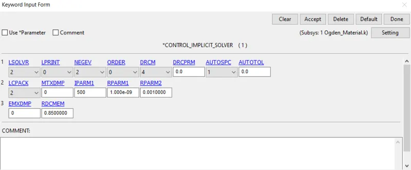
Implicit solver:
These Linear solver cards apply to implicit calculations and that performs matrix inversions
EQ.2: Parallel multi-frontal sparse solver (default)
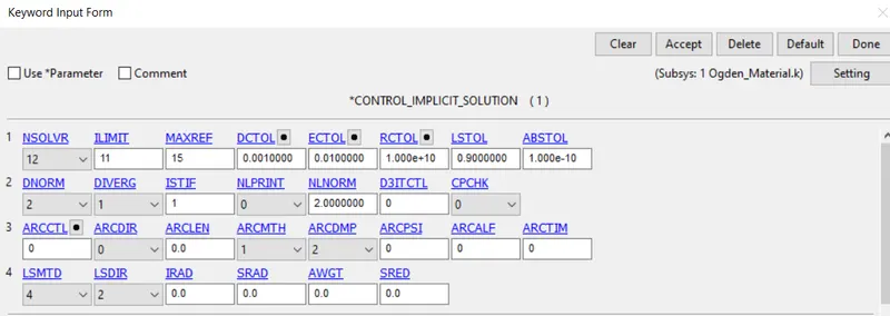
Implicit solution:
Control implicit solution activates the Non linear analysis and in this we use the default values as EQ.12: Nonlinear with BFGS updates + optional arclength.
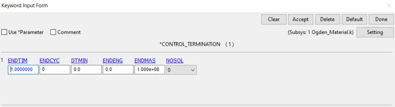
Control_Terimination:
8.Database:
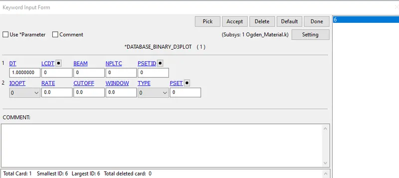
BinaryD3plot:
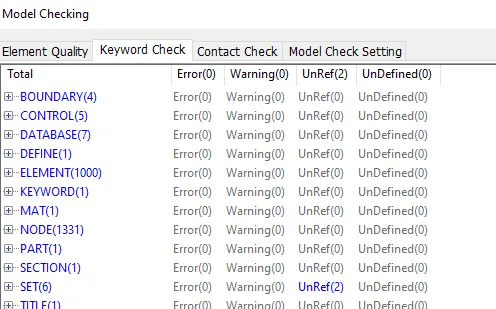
9.Model checker:
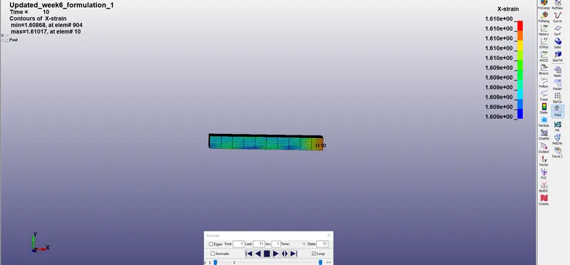
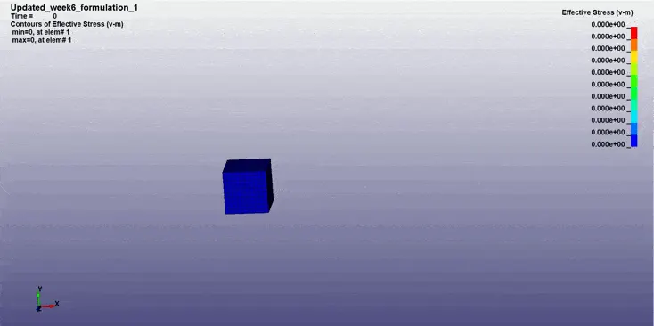
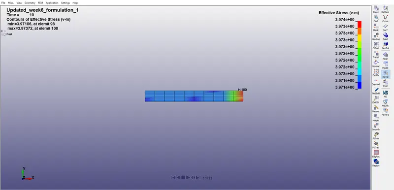
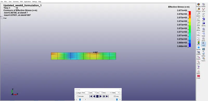
Max vonmoises stresses occurs at the 3.97N/mm^2.
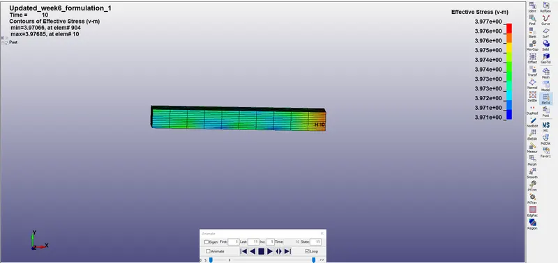
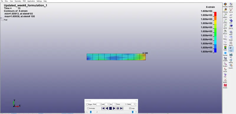
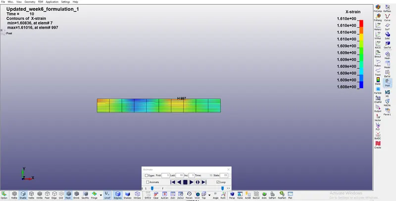
Strain in X direction as recorded as the 1.610e+00
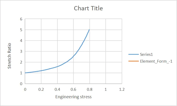
Coverting the True stress and True strain values to the Engineering stress and engineering strain
- True stress= engineering stress*(1+engineering strain)
- True strain= ln(1+engineering strain)
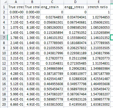
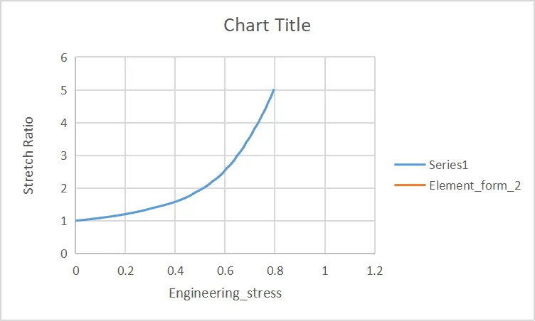
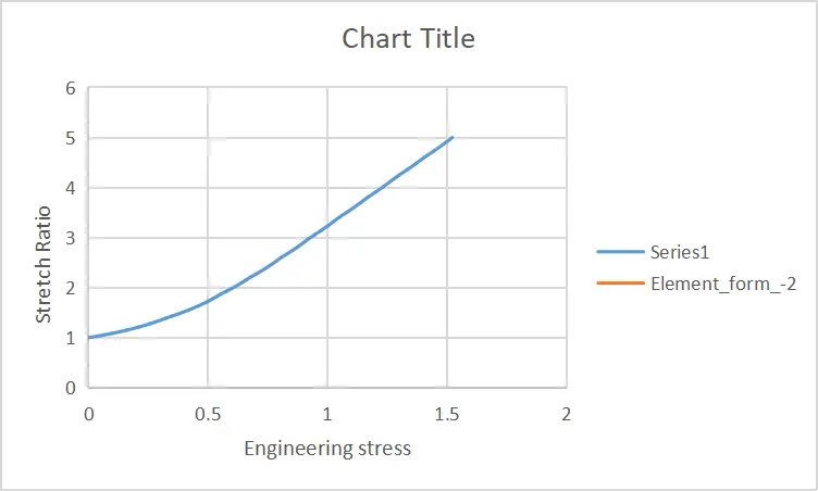
- We used to calculate engineering stress, engineering strain and stretch ratio for the each and every element formulation which ever we have done.
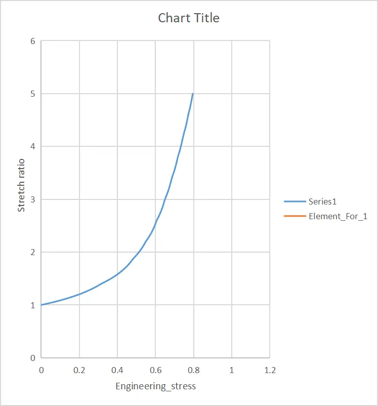
- From that we use to plot the engineering stress and stretch ratio for different element formulations.
- The results from the element formulations are giving almost same in all the plots beacuse the we have simulated an simple model with small load and boundary conditions. whenever we simulate the high non linear analysis it should make an difference in their element formulations.
Element Formulation_2:
Formulation_-1
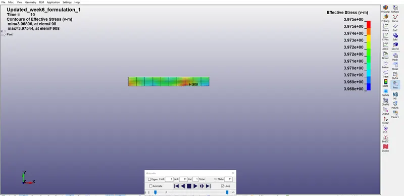
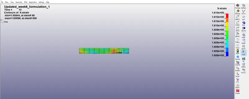
Formulation_-2
Conclusion:
- In this I have created the solid block of 10mmx10mmx10mm dimension with 10 elements for each direction and use the material card attached (Ogden_Material.k).
- By using the Apporiate boundary conditions we have created the Tensile behaviour to the model in Uni axial direction.
- We compare the results for the simulation using different Element Formulations known as 1, 2, -1, -2.
- In this we use the solver as Implicit because the load rate is slow, the applied displacement values are also less and by using this method we can get the accurate Results for the model.