Week 6
Aim:
To understand, select and deploy proper connections between various elements in the given model.
Procedure :
- First step is to open the model. For opening click on File > Input > NASTRAN. Then the model will load showing the FE data log. After the model is loaded, Try and understand the FE model.
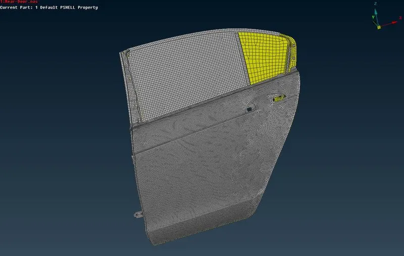
Fig:-1 Showing the initial data ( imported FE model)
- Next step is to create the properties for different elements in the model since the whole model is given in single PID
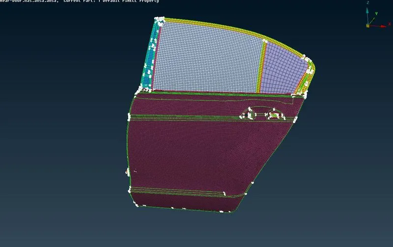
Fig:-2 Showing the model ( having different PIDs assigned)
- Next step is to create bolt connections at the door hinge fittings. create a 3D point using on COG option in Points tab in TOPO module. The 3D points needs to be converted into bolt connection. For convertion click on Assembly > Convert. Then a window will pop up for selection. After selection it will take you to window asking kind of conversion you need. Click on bolt type. Then a bolt connection will appear.
- For bolt connection to be realized in model, there is a need to specify which components are getting connected. This can be done by clicking on Connection manager. A connection selection assistant will appear. Then click on the bolt. It will take you to a window asking to specify whichever components needs to be connected. Specify the parts to be connected and select the FE type as Bolt. Then click on apply and realize, Bolt connection will appear in the model.
- Bolt can also be modelled with the help of multi node RBE2 and two node RBE2 elements. Holes will be given connection with multi node RBE2 and two node RBE2 is used to connect the master nodes of holes.
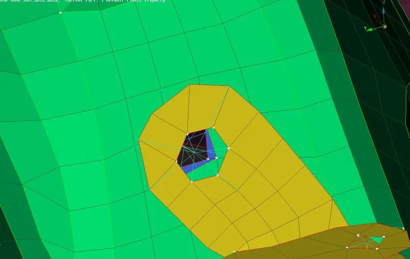
Fig :-3 Showing the Bolt connection representation
- All hinged fittings will be deployed with the bolt connections as represented in the above image.
- RBE2 elements are used for given connections in thehole areas. This can be done by clicking on NASTRAN deck. In that click on RBE2 > multi nodes option in Elements tab.
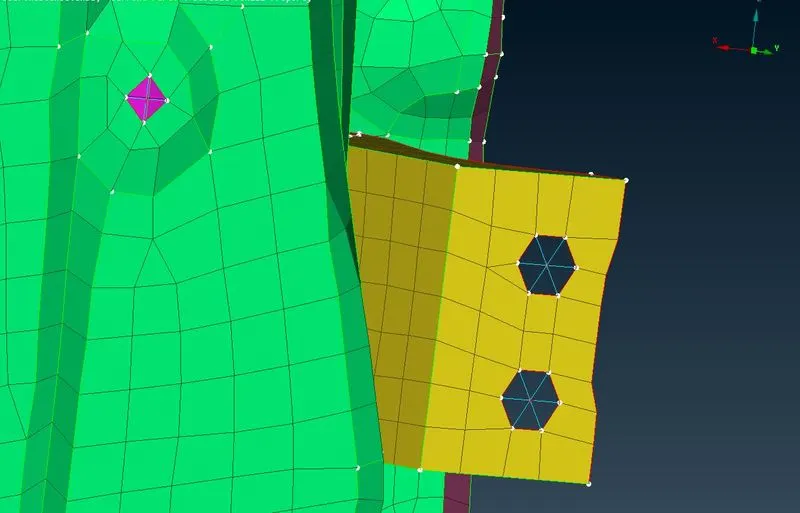
Fig:-4 Showing Connection for the hole
- In some locations spot welds needs to be deployed. This can be done by create a 3D point using on COG option in points. Then this point can be converted into spot weld point using convert option in assembly. Spot weld can be realized in the model using connection manager. In connection selection assistant there is a need to specify the parts which needs to be spot welded together. After selection of parts, in FE type select RBE3-HEXA-RBE3. It will prompt to create a solid element. After selection of parts and solid element creation, spot weld will be successfully created.It can be realised in model by clicking on apply and realize.
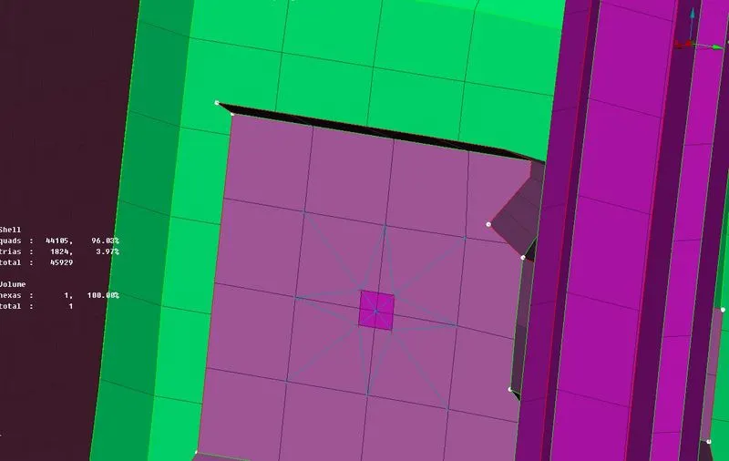
Fig :-5 Showing parts joined using spot weld
- Two parts can be connected using bolt connection or spot weld if its required. Otherwise with the help of RBE2 elements they can be connected. This can be done selecting the nodes of both parts at a single time. This is called cluster node RBE2.
- Parts can be connected by using seam weld connection if required. This can be done by generating the curve and convert that curve to seam line. For giving connection between two parts click on connection manager and select the seam line. Then a connection selection assistant will pop up asking to select which parts needs to be connected. After selecting parts, Select the FE type as Overlap shell. In that give search distance and mention weld thickness and step length. Assign PID then click on apply and realize. Seam weld will be generated between given parts.
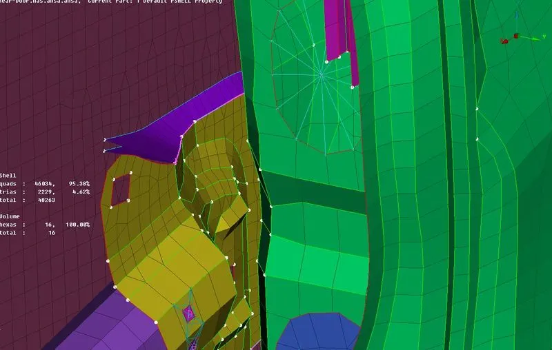
Fig :- 6 Showing the seam weld connection
- In the given model , Door handle is modelled as point mass. This can be done with help of an option called Conmi in Elements tab in NASTRAN deck. First we need to deploy the Multinode RBE2 in the both ends of handle and one more multinode RBE2 needs to be deployed in between these end generated master nodes.After this click on Conmi> Conm2> Nodes. Then a window will pop up asking for mass to be deployed on to that particular node. Remember to give mass in tonnes.
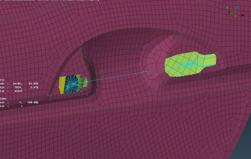
Fig :-7 Showing Con mass representation of Door Handle
- Next important part of connection is to give connections for the glass area. Since the glass is not rigidly bolted or welded to anything it should be connected in a manner which represent the glass beed in physical car. This can be done with help of CBUSH elements which have elastic stifness in all the 3 directions.
- First we need to extract the curve of the glass geometry. This can be done by using Feat2curv. option in perimeters tab in Mesh deck. Then the generated curved should be converted into spot line. This can be done with the help of convert option in assembly. After the spot line conversion it should be relaised in FE model. For this click on connection manager. Connection selection assistant will pop up. Click on the spot line. Then a connection manager window will pop up asking for parts to be connected.
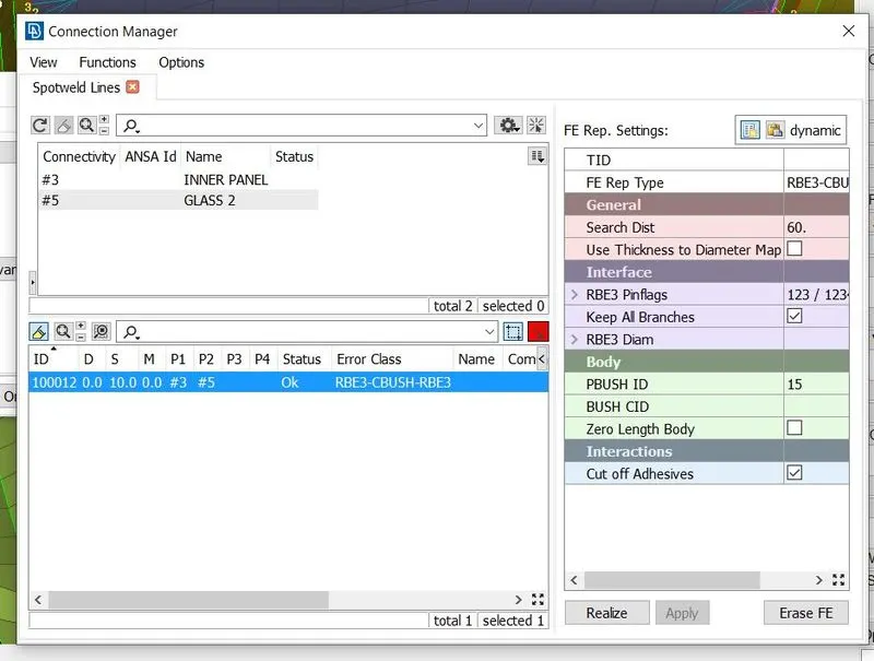
Fig :- 8 Showing the connection manager.
- Select the parts by clicking on P1 and P2. Also mention the distance between each spring element by giving value to S. After click on FE Rep Type and select the RBE3-CBUSH-RBE3 .Give some search distance and check the keep all branches option. In PBUSH ID, new bush id needs to be created. Then click on Apply and Realize. BUSH elements will be realized in the model.
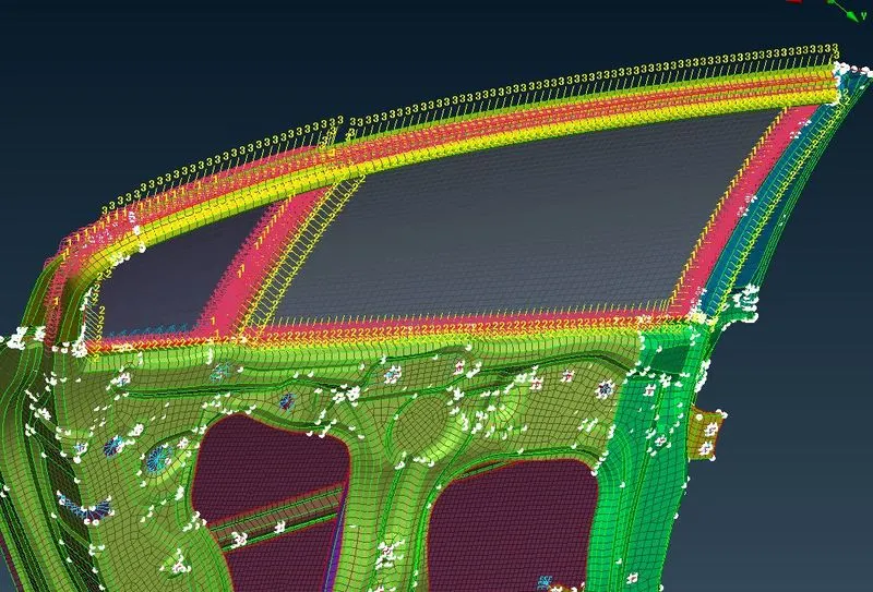
Fig:-9 Showing CBUSH connection around the Glass.
- The generated CBUSH elements are not alligned in a proper manner. For alligning these elements, select all the elements and right click >modify. In that change the oreintation with respect to CID and give CID value as zero. This will make all elements to orient with respect to Global Coordinate System.
Conclusion:
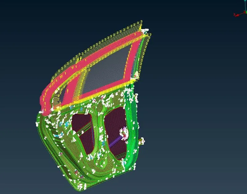
Fig:-10 Showing initial model (without connections) Fig:-11 Showing final model with all connections
Learning Outcomes:
- Understanding different types of connections
- Significance of RBE2 and RBE3 elements
- How to deploy different types of connections