Week 5 Sphere pressing on a plate
SIMULATION OF SPHERE PRESSING OVER A FLAT PLATE USING ANSYS WORKBENCH
OBJECTIVE
To simulate a sphere pressing on a flat plate by following the required conditions.
- To use Structural Steel for both sphere and plate but the material of the plate is Non-Linear.
- To press the sphere onto plate 4mm downwards and retract it.
- To capture the plastic deformation.
1. THEORY
In manufacturing operations, numerous parts and components are formed into different shapes by applying external forces to the workpiece, typically by means of various tools and dies.
Metals may be plastically deformed at room, warm, or high temperatures, their behavior and workability depends largely on whether deformation takes place below or above the recrystallization temperature of the metal. Deformation at room temperature (cold working) results in higher strength, but reduced ductility; generally, it also causes anisotropy (preferred orientation or mechanical fibering), whereby the properties are different in different directions. Cold working has previously been referred to as strain hardening; its effect is to increase strength and reduce ductility. It can be used on both pure metals and alloys. It is accomplished during deformation of the work part by one of the shape forming processes.
In this project, a sphere is made to press a flat plate made of structural steel non-linear material to a depth of 4 mm downwards and retract it. After the sphere is retracted, the results are analysed to check whether the plate material has deformed plastically. Due to symmetry of the model, for saving computational time, only quarter portion of sphere and plate is considered for analysis.
2. ANALYSIS SETUP
2.1 Geometry:
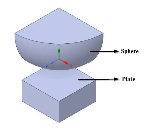
Fig.2.1 3D model of sphere and plate.
The given 3D model of sphere and plate is imported into SpaceClaim. For saving computational time, only quarter portion of the symmetrical sphere and plate is considered for analysis.
2.2. Material Properties:
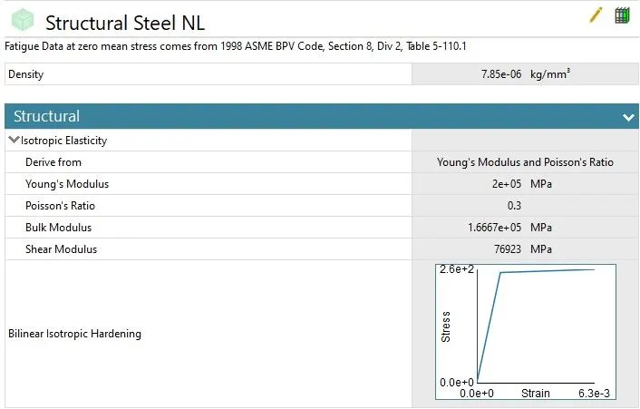
Fig.2.2. Material property details of flat plate.
The material assigned for flat plate is structural steel NL and for sphere is Structural Steel.
2.3 Symmetry Region:
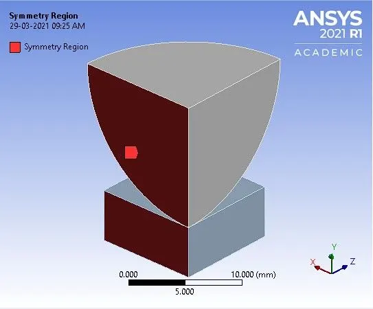
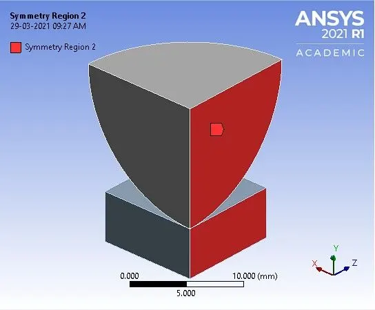
a. Symmetry region normal to Z-axis. b. Symmetry region normal to X-axis.
Fig.2.3 Symmetry regions of sphere and plate.
The symmetry region in fig. 2.3(a) and fig. 2.3(b) are normal to Z-axis and X-axis respectively.
2.4 Contact Details:
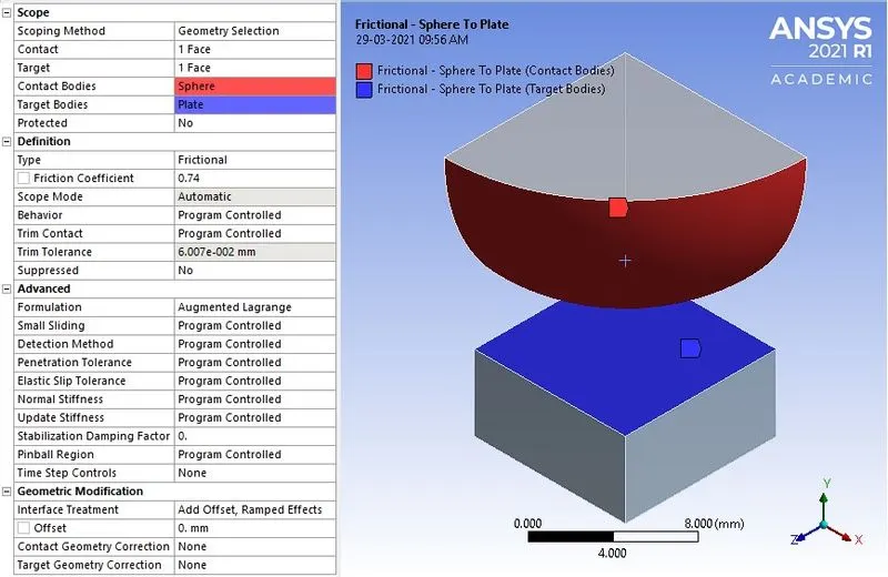
Fig.2.4 Contact details of sphere and plate.
Contact between, sphere (contact body) and plate (target body) are assigned as frictional contact with coefficient of friction = 0.74. The formulation type of contact is set as ‘Augmented Lagrange’.
2.5 Meshing:
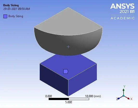
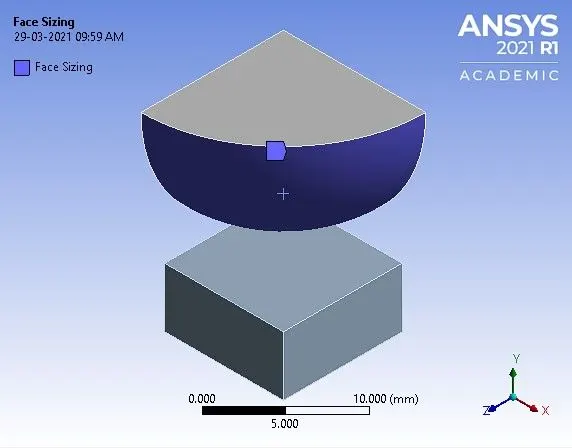
a, Body sizing of plate. b. Face sizing of curved surface of sphere.
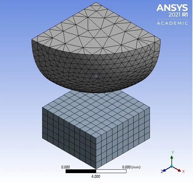
c. Meshed model.
Fig.2.5 Meshing details of sphere and plate.
The element size of curved surface of sphere and whole flat plate is set as 1 mm using face sizing option. The total number of nodes and elements generated are 5581 and 2065 respectively.
Note: The academic version of software has the problem size limit of 128k nodes or elements.
2.6 Boundary Conditions:
2.6.1 Analysis settings:
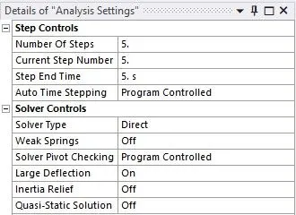
Fig.2.5.1 Analysis settings.
In the analysis settings the number of steps considered is 5. In solver controls, solver type selected is ‘Direct’ and large deflection is set to ‘On’.
2.6.2 Boundary condition for sphere pressing flat plate:
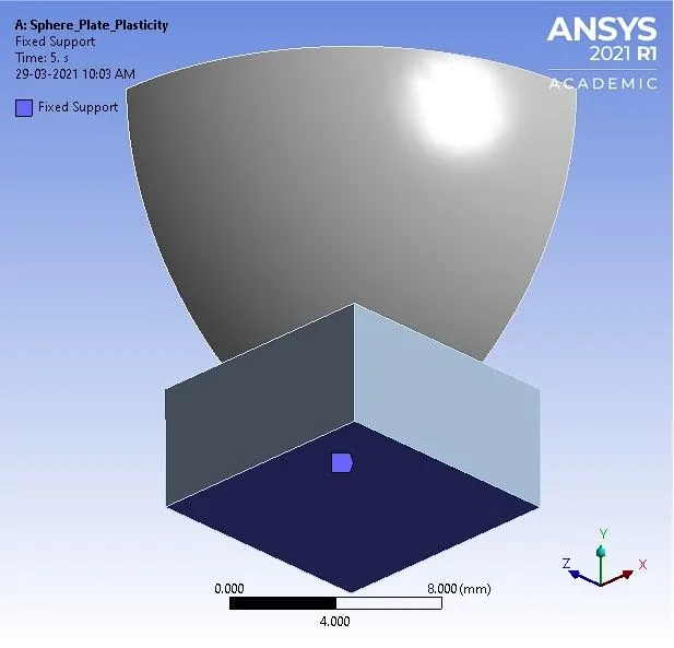
a. Bottom surface of plate is fixed.
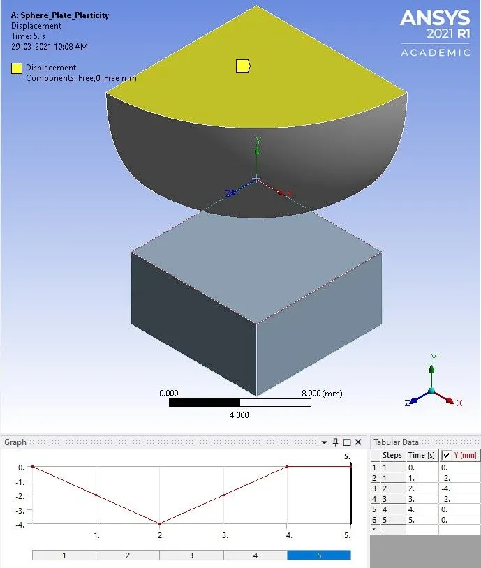
b. Displacement applied on sphere in negative Y-direction.
Fig.2.6.2 Boundary conditions for sphere pressing flat plate.
In order to press the sphere onto the plate 4 mm and retract it, displacement is applied to surface of sphere in negative Y-direction as shown in fig 2.6.2 (b). The bottom surface of the flat plate is fixed.
3. RESULTS AND DISCUSSIONS
3.1 Directional deformation along Y-axis for the whole setup:
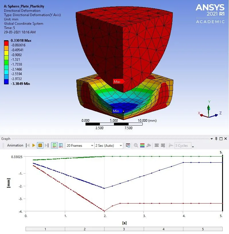
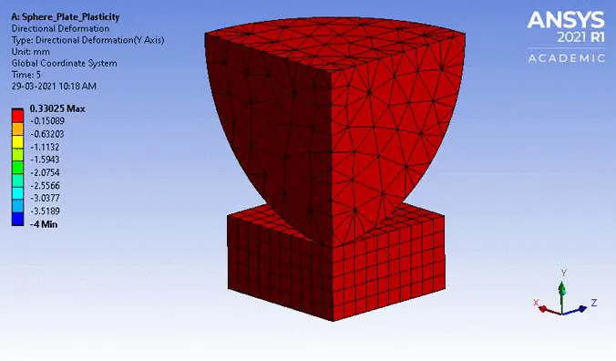
From the above plot, at step 2, it is observed that the sphere has moved from its initial position to a depth of 4 mm downwards.
3.2 Equivalent stress for the whole setup:
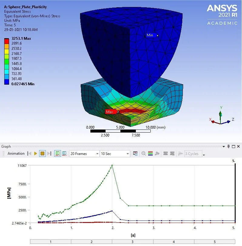
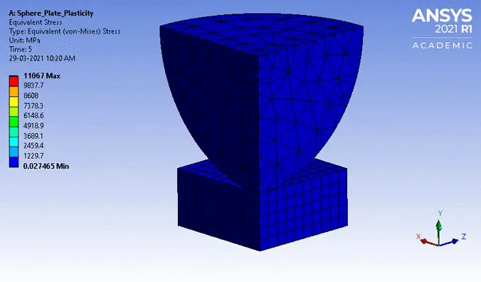
From the above figure, the equivalent (v-m) stress developed in the plate reaches a maximum value of 11067 MPa at time 2 s and later decreases and reaches a steady value of 3253.1 MPa as the sphere is retracted back to its initial position.
3.3 Equivalent Elastic strain for the plate:
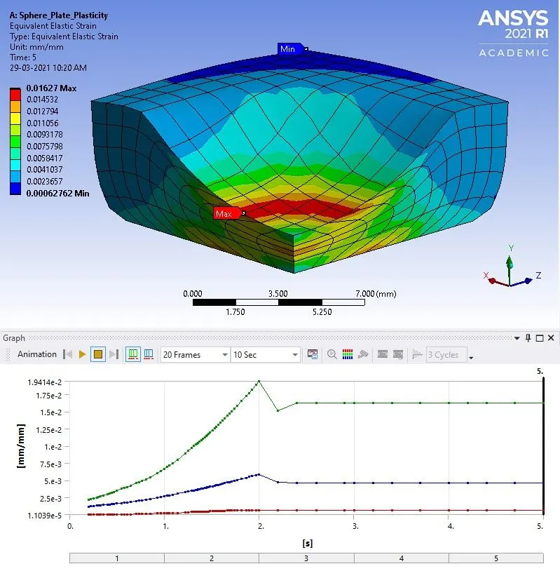
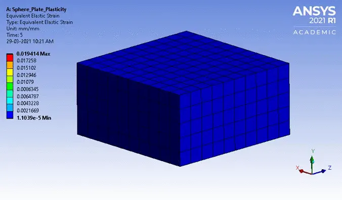
From the above figure, the equivalent elastic strain induced in the plate reaches a maximum value of 0.019414 at time 2 s and later decreases and reaches a steady value of 0.01627 as the sphere is retracted back to its initial position.
3.4 Equivalent Plastic strain for the plate:
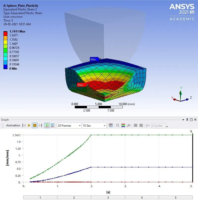
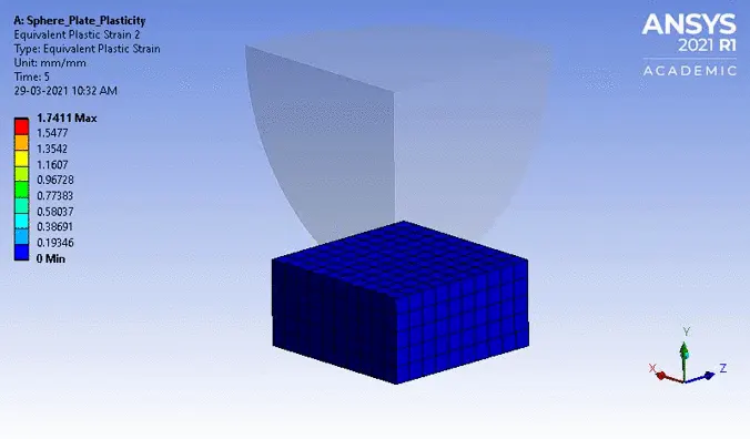
From the above figure, the equivalent plastic strain induced in the plate reaches a maximum value of 1.7411 at time 2 s and remains steady as the sphere is retracted back to its initial position. Hence, it is evident that the material has plastically deformed.
4. ANIMATION OF RESULTS:
4.1 Directional deformation along Y-axis for the whole setup:
4.2 Equivalent stress for the whole setup:
4.3 Equivalent Elastic strain for the plate:
4.4 Equivalent Plastic strain for the plate:
CONCLUSION
- The simulation of a sphere pressing onto a flat plate made of structural steel Non-Linear material was carried out successfully.
- From the results, it is observed that the sphere has moved from its initial position to depth of 4 mm on the plate and retracted back to its initial position.
- The equivalent plastic strain induced in the plate reached a maximum value of 1.7411 at time 2 s and remained steady as the sphere retracted back to its initial position. Hence, the material has deformed plastically.