Week- 5 - Solid meshing
AIM - To Do Solid Meshing On The Given Rear View Mirrior.
OBJECTIVE:
- To check for the geometrical errors on the component.
- Mesh the given component with given 2D element quality criteria.
| S.No | Quality Criteria | Value |
| 1 | Target Element Length | 1 |
| 2 | Minimum Length | 0.5 |
| 3 | Maximum Length | 2 |
- To do Volume Meshing for the given components's volume using tetra mesh by following the below quality criteria.
| S.No | Quality Criteria | Value |
| 1 | Tet Collapse | 0.2 |
- There should be no Kinks and Dips after volume mesh on the surface.
PROCEDURE:
- Fierst the component or the model was imported in ANSA.
- Then geometry cleanup process was done which are discussed below.
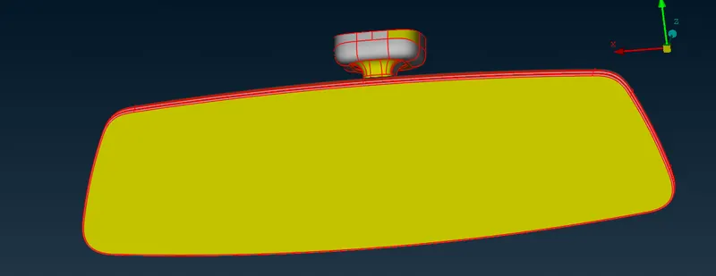
- Cons resolution was done by using command Basic mesh → Perimeters → length (Do Box Selection By left mouse click)→ Hit scroll button and in the popup box put Length = 1. The cons of the component get smoother than befor below are the images of the given process.
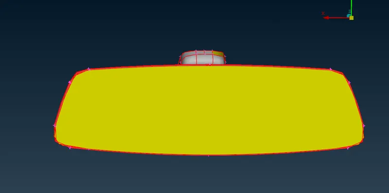
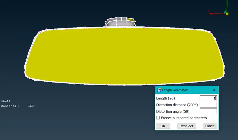
- Smoother cons after the cons resloution process.
- Then from the property tab other parts of the components were hide and one part at a time was worked upon on five parameters scale discussed below.
- Geometry Cleanup.
- Genarating 2D mesh.
- Pre Volume Check.
- Volume Defination.
- Generating 3D mesh.
Below the process for the one part is shown which is repeated for all the parts.
- First the from the List → Property was openend → required part was kept unhidden → from modules Topo was selected. Then From Faces → Topo (Box selection on the component to fix the single cons to doube cons). Then Faces → Orientation was done. Below are the images for the same.
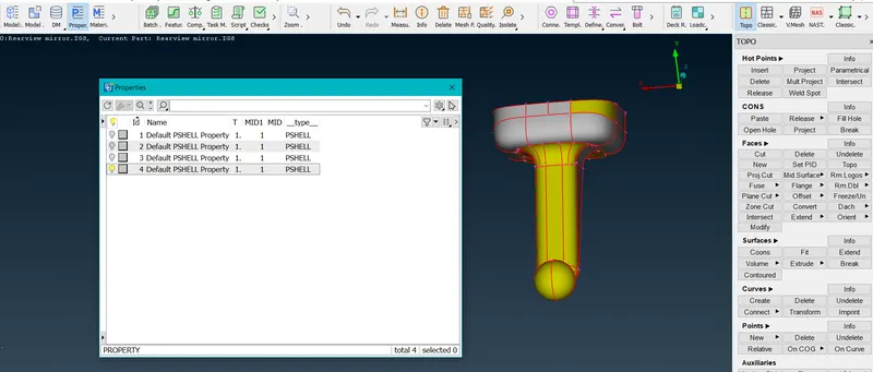
- Single cons are converted to double after Topo operation.
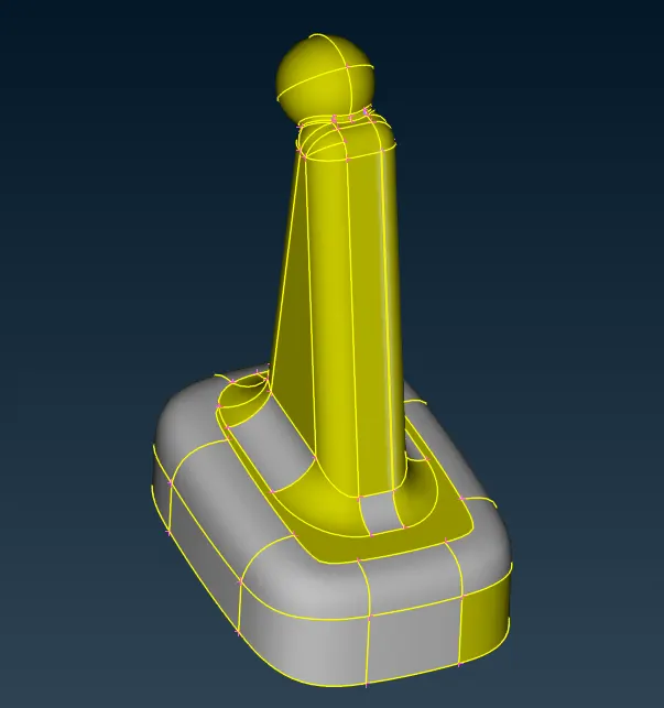
- After Orientaion.
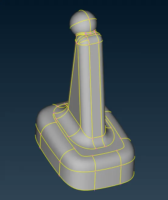
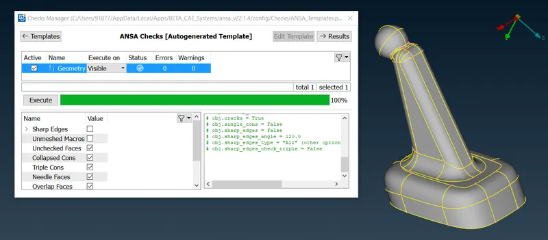
- Then Geometry check ws done using command Tool → Checks → geometry → Execute (Select triple cons before executing). Below is the image for the same.
- Then the quality criteria settings were done by pressing f11. parameters were set for both 2D and solids as demanded in objective above. After that mesh parameters setting was also done by going to utilities → mesh parameters.
- Then checked the distance between cons to check where the elemenst can fail for minimum length quality criteria. Accordingly the cons were suppressed.
- Then 2D meshing was done by using command classic mesh → Mesh Generation (Choose Best) → select all the flat surfaces and mesh them with trias only from option list select elements types Trias only. Then mesh the curve surface with ortho trias by selecting the elements type ortho tria from the option list.
- Then reconstructed the areas where the elements were failing the quality and after reconstruction smooting was also done.
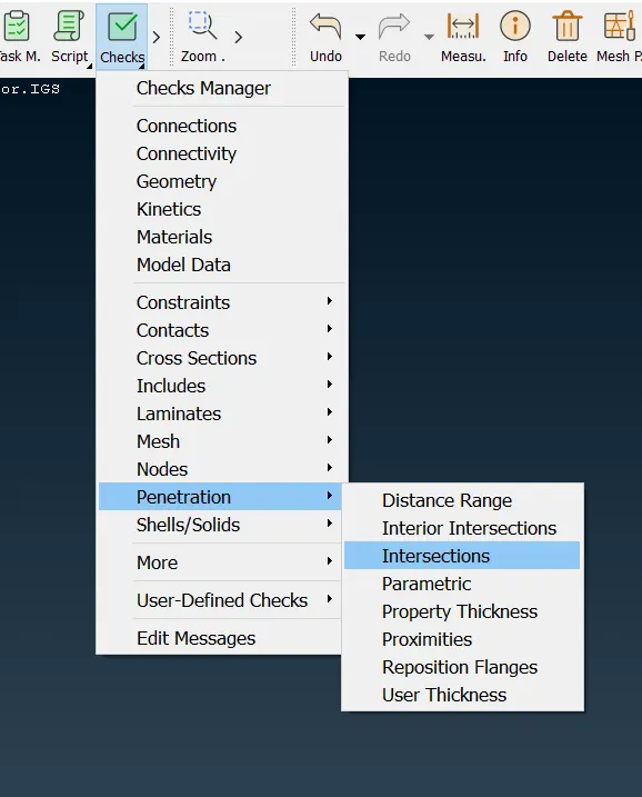
- Then did the penetration and intersection check before volume meshing. Below is the image for the same.
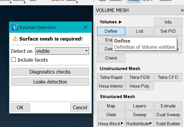
- After succesfully completing the above step moved to modules → volume mesh → defien volume → Detect visible → press ok. If no errors came the every thing is ok and volume mesh can be done using Unstructured mesh → Tetra Rapid. Below are the images for the same.
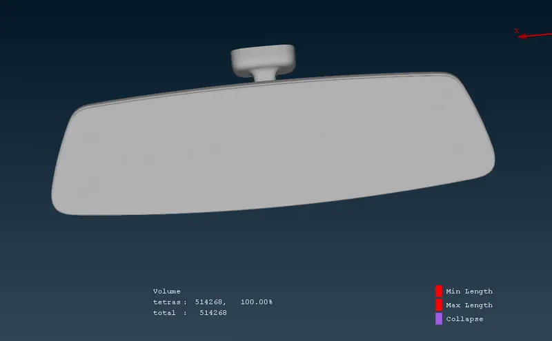
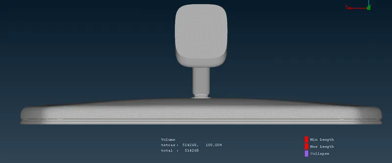
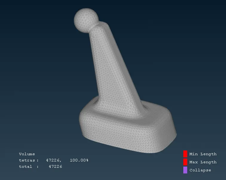
- After completing the volume mesh the component parts looks as shown below.
- The same process was followed for all the parts of the components as discussed above.
CONCLUSION:
- All the above objectives were achieved.
- The 3D mesh was generated from 2D mesh using tetra mesh.
- No kinks and dips after volume mesh were observed on the surface.
FINAL MODEL IMAGES: