Week 5 - Rayleigh Taylor Instability
AIM:
Explain how these mathematical models have been adapted for CFD calculations.
OBJECTIVES:
- What are some practical CFD models that have been based on the mathematical analysis of Rayleigh Taylor waves? In your own words, explain how these mathematical models have been adapted for CFD calculations.
- Perform the Rayleigh Taylor instability simulation for 2 different mesh sizes with the base mesh being 0.5 mm. Compare the results by showing the animations( Attach them from your google drive). Observe the differences in the animation and explain the effect of mesh size on the simulation. Also, explain why a steady-state approach might not be suitable for these types of simulations Choose Air and Water for this simulation]
- Run one more simulation with water and user-defined material(density = 400 kg/m3, viscosity = 0.001 kg/m-s) for refined mesh.
- Define the Atwood Number. Find out the Atwood number for both cases and explain how the variation in the Atwood number in the above two cases affects the behavior of the instability.
INTRODUCTION:
Fluid instabilities show up everywhere in nature. Fluid flow will start off laminar and smooth and then quickly transition to an irregular pattern eventually transitioning to turbulence.
Some practical CFD models that have been based on the mathematical analysis of Rayleigh Taylor waves are below,`
Stratified fluid instabilities:
From a fluid instability perspective, stratified fluid systems are in some ways the easiest to understand and visualize. When there is a fluid system in which two fluids with different properties, an unstable configuration can be realized. In this case, there is a clear boundary between two fluids and this can be extended to a continuous variation between fluids, but the diffusion effects would damp out any perturbation and instability, so would not be as pronounced.
Buoyancy driven instabilities:
Buoyancy-driven fluid instabilities occur in a stratified fluid system when the light fluid is accelerated into the heavier one often by means of a pressure gradient.
Some practical CFD models that have been based on the mathematical analysis of Rayleigh Taylor waves are:
Kelvin-Helmholtz instability:
The Kelvin–Helmholtz instability typically occurs when there is velocity shear in a single continuous fluid, or additionally where there is a velocity difference across the interface between two fluids. A common example is seen when wind blows across a water surface, the instability constantly manifests as waves.
Plateau–Rayleigh instability:
The Plateau–Rayleigh instability explains why and how a falling stream of fluid breaks up into smaller packets with the same volume but less surface area. The driving force of the Plateau–Rayleigh instability is that liquids tend to minimize their surface area by virtue of their surface tensions.
Rayleigh-Taylor instability:
The Rayleigh-Taylor instability is a buoyancy-driven instability where the acceleration is constant with respect to the fluid flow time. An important example of Rayleigh-Taylor instability is when a heavy fluid lies atop a light one while in the presence of a downward-acting gravitational field.
Richtmyer–Meshkov instability:
The Richtmyer–Meshkov instability occurs when two fluids of different densities are impulsively accelerated. Normally this is done by the passage of a shock wave. The development of the instability begins with small amplitude perturbations which initially grow linearly with time. This is followed by a nonlinear regime with bubbles appearing in the case of a light fluid penetrating a heavy fluid and with spikes appearing in the case of a heavy fluid penetrating a light fluid.
CASE 1:
Rayleigh Taylor instability simulation for base mesh 0.5 mm :
Step 1-Geometry creation :
BASELINE MODEL:
- Now, the RT instability simulation for a 2D model is performed using air and water as the two fluids.
- Assign the dimensions to 20x20 mm for each plate.
- select both fluid volumes area share using share topology.
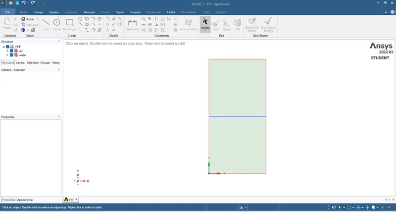
STEP 2:
For the Meshing, an element size of 0.5 mm was used for the baseline case. The elements we have by default are quadratic which is good.
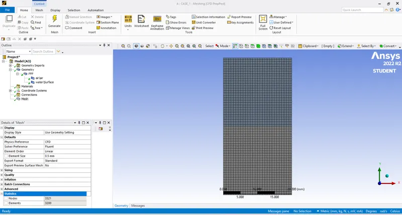
Step:3
Setup and solution:
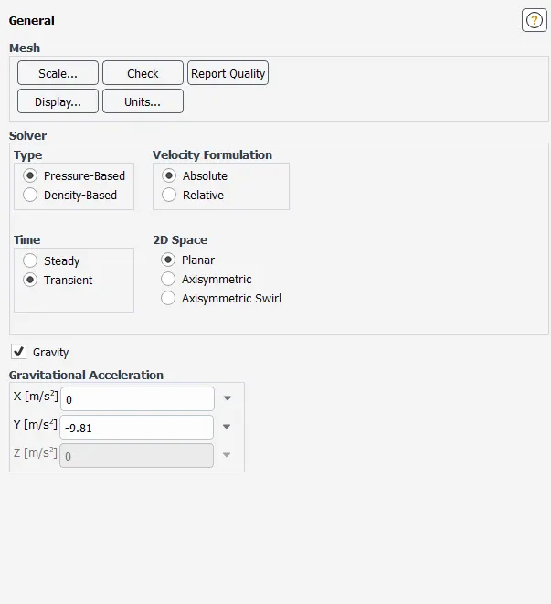
We will set up the solver type to pressure based. where we will set the time to transient and apply gravity in the negative Y
direction.
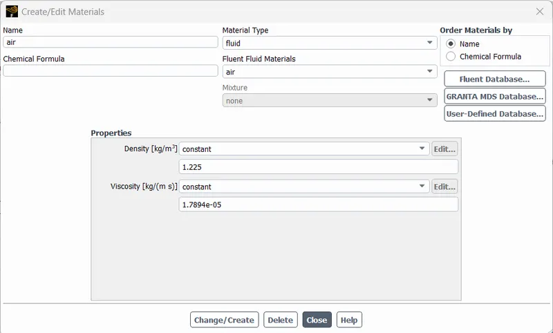
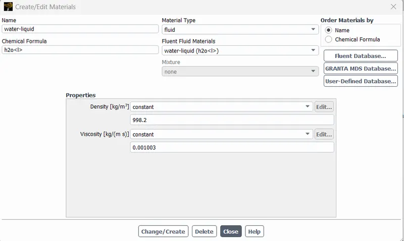
here we have two materials first is the air and another is water, both having all the default properties set by fluent.
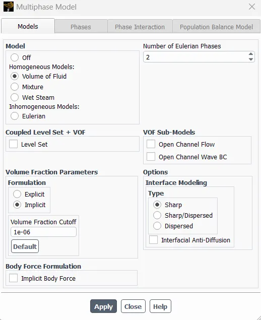
we will set the viscous model to laminar and for the calculation, in multiple phases, we will be using the volume of the fluid model,
with implicit formulation for the volume of fluid parameters.
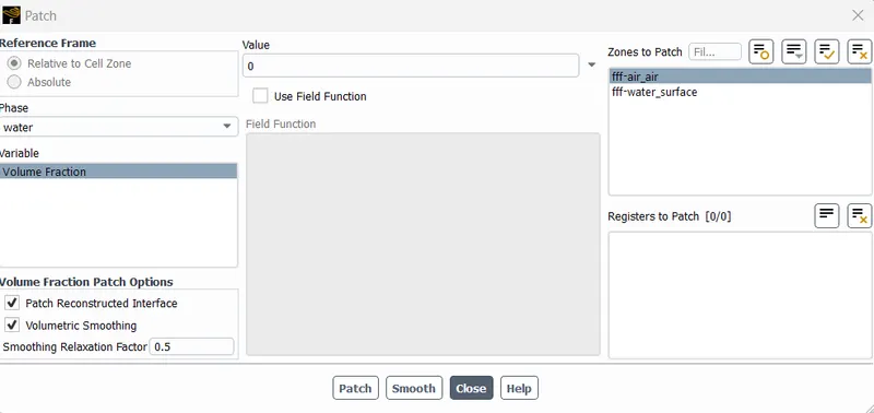
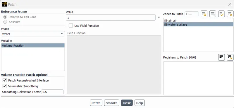
to initiate the simulation we will be hitting the initialize button and then patch the solution. while patching we select the phase to water and the variable as volume fraction and use value '0' for the air surface zone and use value '1' for the water surface zone as shown below.
PATCH FOR AIR _0:
PATCH FOR WATER _1
CONTOUR SETUP:
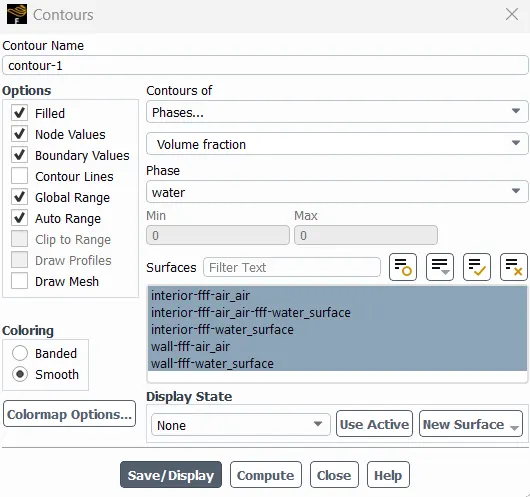
SETUP:
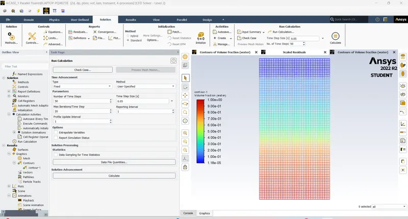
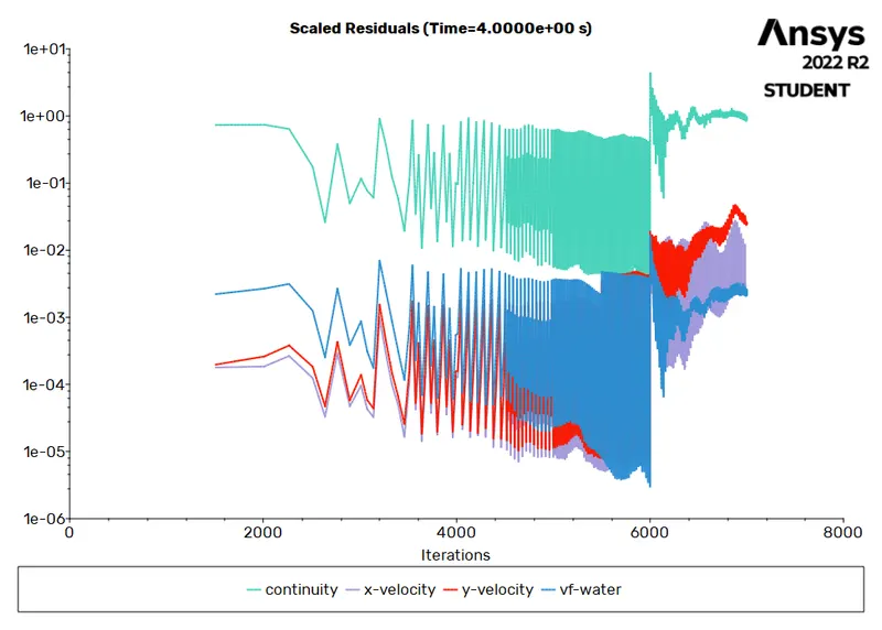
RESIDUAL PLOT:
ANIMATION VIDEO LINK BELOW:
https://drive.google.com/file/d/1JnQj4uT7PCcfVTouJANLLllFjkSq6qIO/view?usp=drive_link.
----------------------------------------------------------------------------------------------------------------------------------
CASE 2: MESH SIZE 0.3 mm
Time step size (sec)= 0.005
No of Time steps: 1500
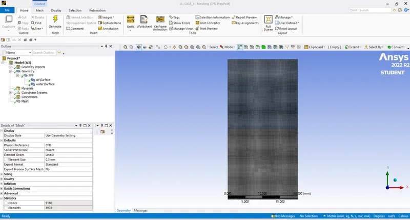
RESULT:
RESIDUAL PLOT:
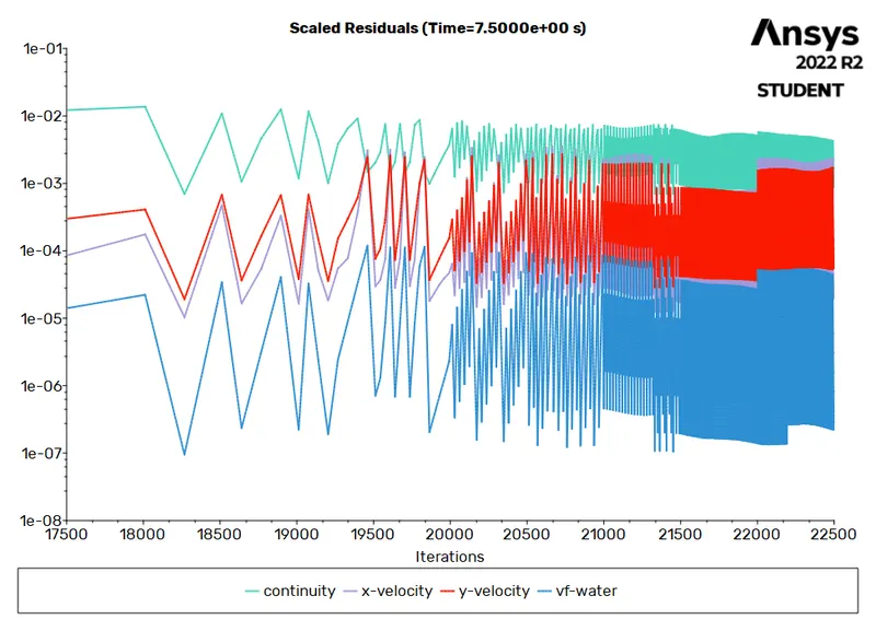
ANIMATION VIDEO LINK BELOW:
https://drive.google.com/file/d/1CsiuhwUtNnY6plYK8tfh95aCeMjTSD5o/view?usp=drive_link.
-----------------------------------------------------------------------------------------------------------------------------
CASE 3: MESH SIZE 0.2
Time step size (sec)= 0.005
No of Time steps:1500
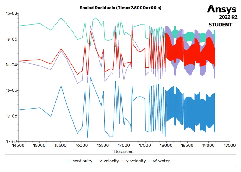
RESIDUALS PLOT:
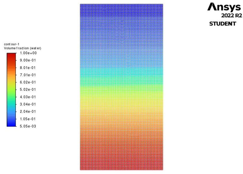
VOLUME FRACTION:
ANIMATION VIDEO LINK BELOW:
https://drive.google.com/file/d/1HlXIuDN_E2c8y7djqqH4ZBGfmXXUOFAL/view?usp=drive_link.
-----------------------------------------------------------------------------------------------------------------------------------
CASE 4:
CHANGING THE MATERIALS :
Running one more simulation with water and user-defined material(density = 400 kg/m3, viscosity = 0.001 kg/m-s) for
refined mesh.
Time step size (sec)= 0.005
No of Time steps : 1500
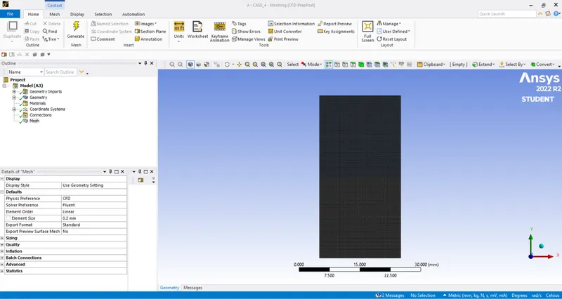
MESHING:
RESIDUAL PLOT:
VOLUME FRACTION:
ANIMATION VIDEO LINK BELOW:
https://drive.google.com/file/d/1gR4ihRKqbTMKBNxSVSNyvVqn0_wn1u3w/view?usp=drive_link.
OBSERVATION :
- The finer mesh captures the instability better than the coarse mesh.but it takes more time for the heavier fluid to settle down.
- The computational time is also increased for fine mesh but the result obtained having better accuracy.
- The steady state simulation is performed if we are concerned more about the final state results or the equilibrium state,
- In RT instability CFD model we are more concerned to learn about the transition of the irregularities that start developing when we pour the high densiy fluid upon the low density fluid under the effect of gravity and we want to know how the interface collapses as a function of time so In this case Transient state is more suitable over the steady state.
- For the water and user defined material the bubbles formed are smaller due to lesser difference between the densities of both the fluids
Atwood Number:
It is a dimensionless number that is used to study hydrodynamic instabilities in density stratified flows.
It is denoted by letter A
A=ρ1−ρ2ρ1+ρ2→1�=�1−�2�1+�2→1
where,
ρ1�1=Density of heavier fluid `
ρ2�2=Density of lighter fluid
Calculate the Atwood Number for Air-water RT instability
ρ1=998.2kgm3�1=998.2���3 (water density)
ρ2=1.225kgm3�2=1.225���3 (Air density)
The above values are substituting in 'equation 1' we get A=0.9975
Calculate the Atwood Number for Water-UD material RT instability
ρ1=998.2kgm3�1=998.2���3 (water density)
ρ2=400kgm3�2=400���3(User defined material density)
substituting the abovevalues in 'equation 1' we get A=0.4278
we can clearly see that for second case the artwood number is small so the bubbe formed in this case are small as compared
to the bubbles formed for the first case and it take less time to seperate after the instability.