Week 5 - Rayleigh Taylor Instability
Aim of the challenge:
The aim of the challenge is to perform the Rayleigh Taylor instability simulation for 2 different mesh sizes with the base mesh being 0.5 mm.
Objective:
The main objective of the project is to,
- Explaining how the rayleigh taylor mathematical models have been adopted for CFD calculations.
- Comparing the results of different mesh with animation.
- Observing the differences in the animation and explain the effect of mesh size.
- Explaining why steady state approach might not be suitabler for these types of simulations.
- Running the another simulation with water and user-defined material for refined mesh and comparing the results.
- Defining the Atwood Number and Atwood number for both the cases and explaining how the variations in Atwood number in the above two cases affects the behaviour of the instability.
Introdcution:
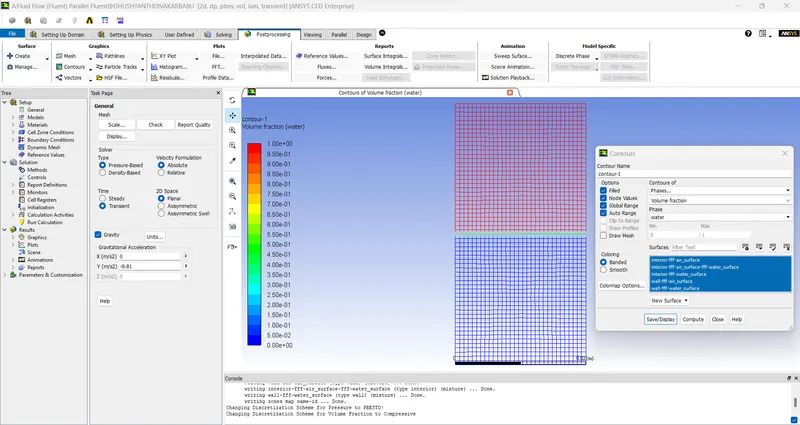
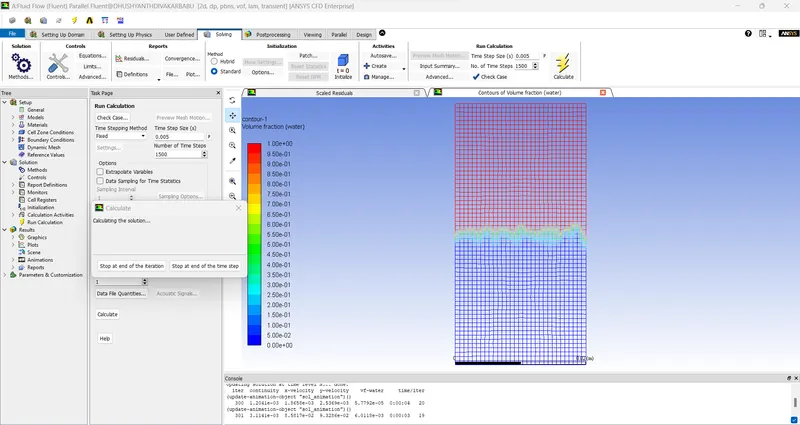
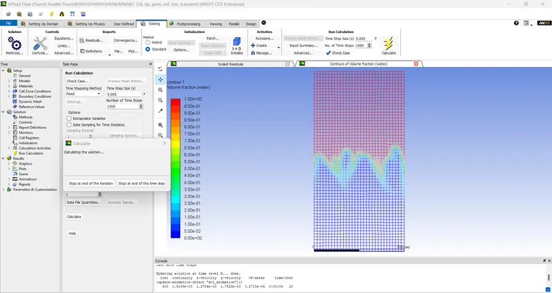
In this project, we are going to perform the two dimensional simulation for two immiscible fluids that have different densities. Initially, the fluid with high density is placed at the top region while the fluid having lesser density at the bottom. Due to gravity, the heavy dense fluid flows downwards making the less dense fluid to go up. This causes the Rayleigh Taylor instability between the interface of those two fluids.
Reason for using Transient state over steady state for this simulation,
Here, we use transient (Unsteady) state for this simulation and not the steady state.
This is because, the steady state simulation gives the final state that is reached by those fluids. So, simulating with steady state will try to solve for the final state solution of the fluids for each iteration.
In transient case, the flow is captured for each time steps which gives the exact solution at that time of the simulation.
CFD models based on the mathematical analysis of Rayleigh Taylor waves:
Rayleigh-Taylor instability :
It is an instability of an interface between two fluids of different densities which occurs when the lighter fluid is pushing the heavier fluid.
For example,
- If the water is suspended above oil which has less density than water, due to gravity, the heavier dense water flows downwards which makes the oil to go upwards.
Richtmeyer-Meshkow instability :
This instability occurs when a shock wave interacts with an interface separating two different fluids or in other words when two fluids of different densities are impulsively accelerated.
Plateau-Rayleigh instability :
This instability explains why and how a falling stream of fluid breaks up into smaller packets with the same volume but different or small surface area.The driving force of this instability is that the liquids by virtue of their surface tensions ,tends to minimize their surface area .
Kelvin-Helmholtz instability :
This instability can occur when there is velocity shear in a single continuous fluid, or where there is a velocity difference across the interface between two fluids.
For example,
- Wind blowing over the water
- Cloud formation
Procedure:
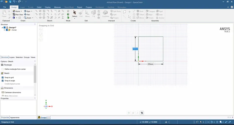
1. we consider a simple 2D geometry of which,
- Draw 2 squares one above the other with a length of 0.02 m.
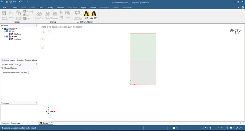
- Then naming the below square as air and above square as water in 2 different components.
- And share the topology for a perfect intersection between both surfaces.
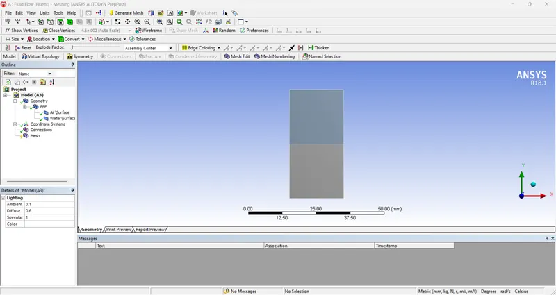
2. Open mesh interface and generate mesh.
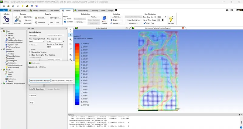
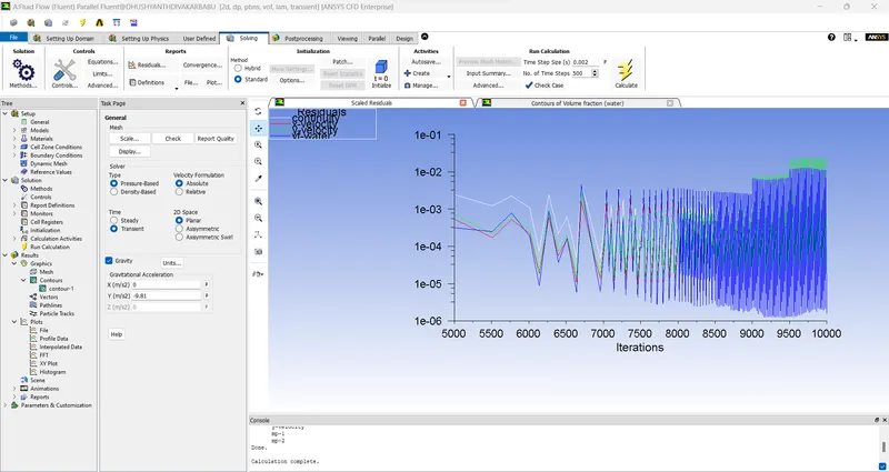
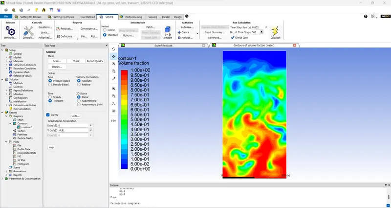
Case 1:
Solver type - Pressure based
Solver time - Transient
Velocity formulation - Absolute
Viscous model - Laminar
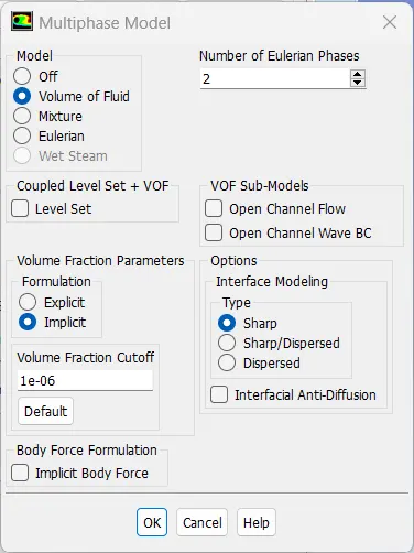
Multiphase - Volume of fluid: Implicit formulation - 2 phase
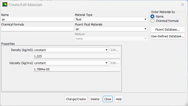
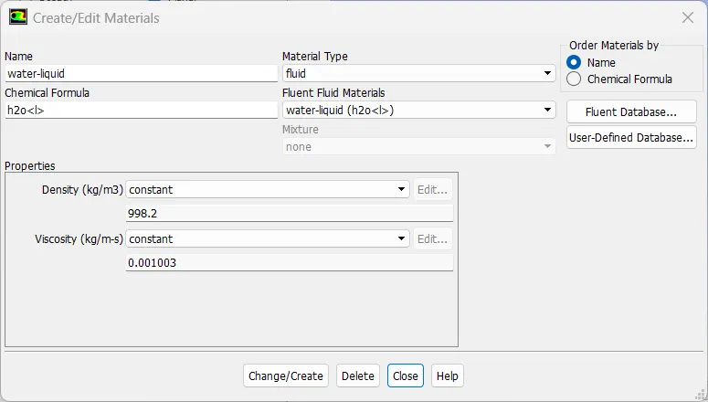
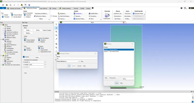
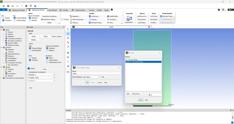
Fluid Material type - Air and water
Solid material type - Aluminium
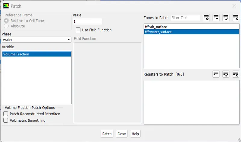
Initialization - patch 1: Water -surface ( 1 value for volume fraction of water) and Air-surface (0 value of volume fraction of water).
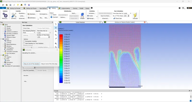
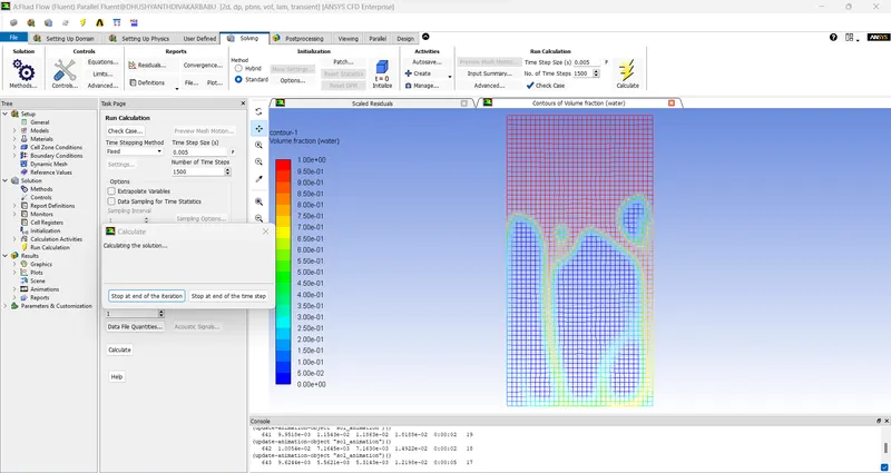
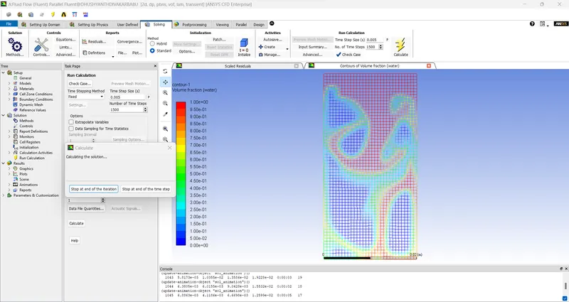
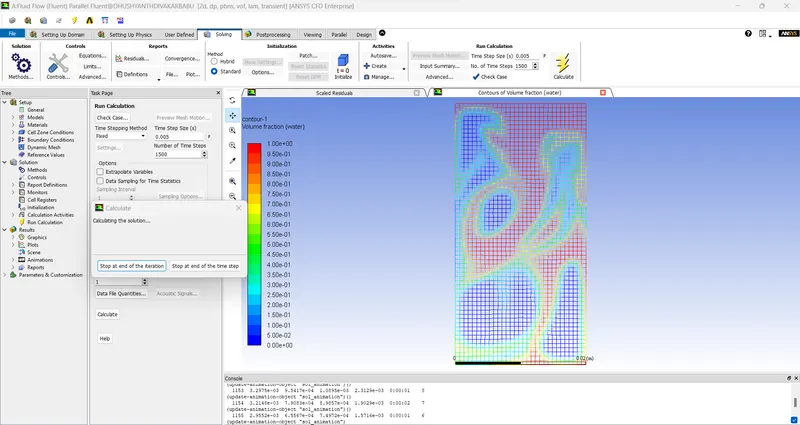
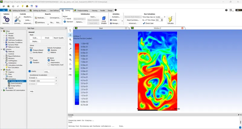
Mesh size - 0.5 mm
Number of nodes: 1830
Number of elements:
Case 2:
Solver type - Pressure based
Solver time - Transient
Velocity formulation - Absolute
Viscous model - Laminar
Multiphase - Volume of fluid: Implicit formulation - 2 phase
Fluid Material type - Air and water
Solid material type - Aluminium
Initialization - patch 1: Water -surface ( 1 value for volume fraction of water) and Air-surface (0 value of volume fraction of water).
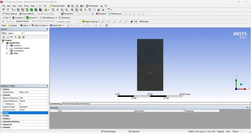
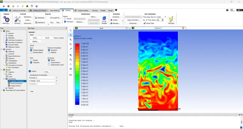
Mesh size - 0.2 mm
Number of nodes: 7875
Number of elements: 7688
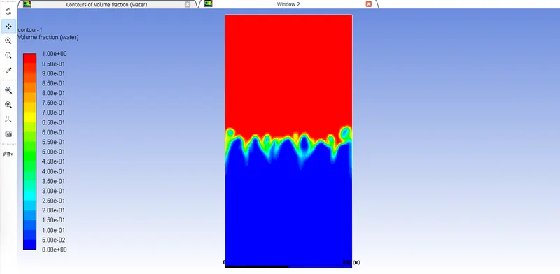
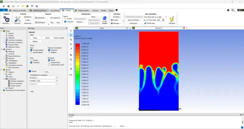
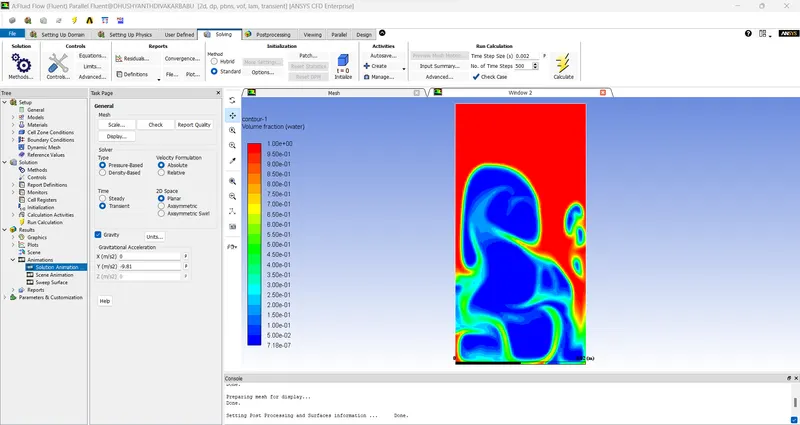
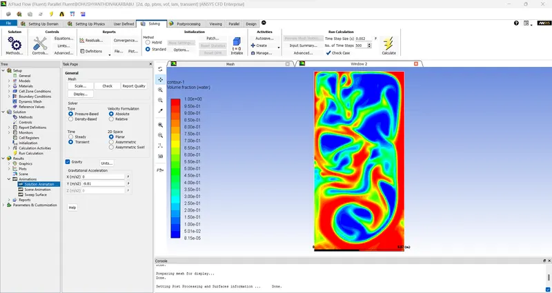
Case 3:
Solver type - Pressure based
Solver time - Transient
Velocity formulation - Absolute
Viscous model - Laminar
Multiphase - Volume of fluid: Implicit formulation - 2 phase
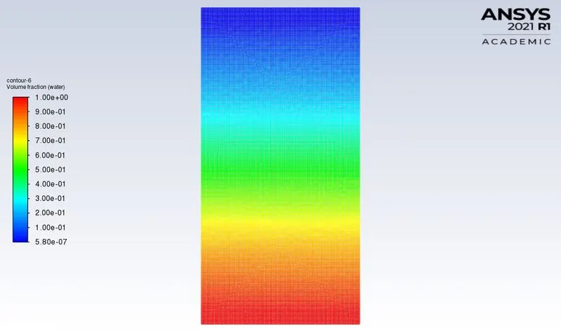
Fluid Material type - user defined material and water
Solid material type - Aluminium
Initialization - patch 1: Water -surface ( 1 value for volume fraction of water) and user defined material (0 value of volume fraction of water).
Mesh size - 0.2 mm
Number of nodes: 7875
Number of elements: 7688
Atwood number:
The Atwood number is a dimensionless number in fluid dynamics used in the study of hydrodynamic instabilities in density-stratified flows.
It is a dimensionless density ratio defined as,
`A = (rho_1 -rho_2)/(rho_1 + rho_2)`
Where,
A = Atwood number
`rho_1` = density of heavier fluid
`rho_2` = density of lighter fluid
Case 1:
Density of water(`rho_1`) = 998.2 `(kg)/m^3`
Density of air(`rho_2`) = 1.225 `(kg)/m^3`
`A = (998.2 - 1.225)/(998.2 +1.225)`
A = 996.975/999.425
A = 0.99755
Case 2:
Density of water(`rho_1`) = 998.2 `(kg)/m^3`
Density of user defined material(`rho_2`) = 440 `(kg)/m^3`
`A = (998.2 - 440)/(998.2 +440)`
A = 558.2/1438.2
A = 0.388124
Grid Independency study:
Case 1: Air and Water - Mesh element size: 0.5mm - Number of Elements: 2024 - Atwood number: 0.99755
Case 2: Air and Water - Mesh element size: 0.2mm - Number of Elements: 7688- Atwood number: 0.388124
Case 3: Air and User defined material of density 400kg/m^3 ansd viscosity of 0.001 - Mesh element size: 0.2mm - Number of Elements: 7688- Atwood number: 0.388124
Conclusion:
From the animations,
For the first two cases of different mesh element size, we can observe that, the Rayleigh instability is captured more accurately in the case which has the finer mesh size(0.2 mm). So, we can say that,
- As we decrease the mesh element size, the even smaller volumes of the fluids can be captured properly, but in contrast, it will also take more computational time running the simulation.
- Therefore, the most optimum mesh element size has to be selected.
For case-3 for Rayleigh instability simulation of water and user defined fluid, 0.2 mm mesh size was chosen.
We can observe that the case with water and air as the fluids, the Atwood number is found to be 0.9975 whereas for water and user defined fluid, it is 0.4278.
- As the difference in densities of the two immiscible fluids increases, the Atwood number also increases which results in higher and faster penetration distance of water into the air.
Animation:
The animation is captured in the 2021 R1 version while the above iteration is done in the 2018 version.
Drive link: https://drive.google.com/drive/folders/1s7uZQxLWZpYwx0l9itWSiBMMi2meGrLC?usp=share_link