Modelling Spotwelds
Aim:
To perform crash simulation for the given meshed bracket modeled using beam elements and solid elements and compare the results.
Solver Deck Setup:
1. Assigning Material and Section Card:
*MAT_PIECEWISE_LINEAR_PLASTICITY_(24) with properties of steel is used as material for the bracket.
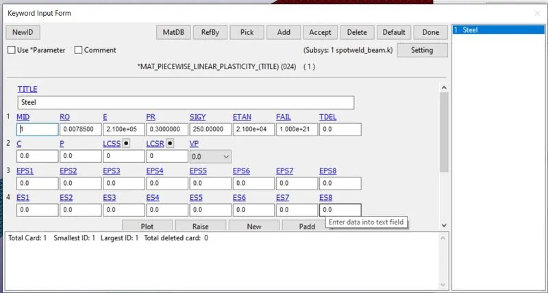
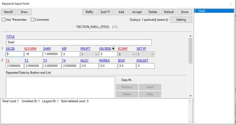
Assign the material and section card to the parts.
2. Creating Beam Element Spotwelds:
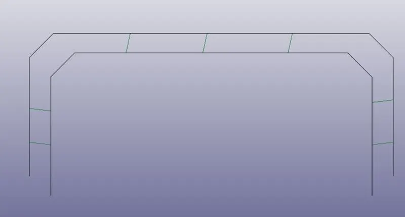
Spotwelds are created using beam elements. To create beam elements go to Element Tools - Element Editing - Elem Type - Beam and select the required nodes to create the spotwelds as shown.
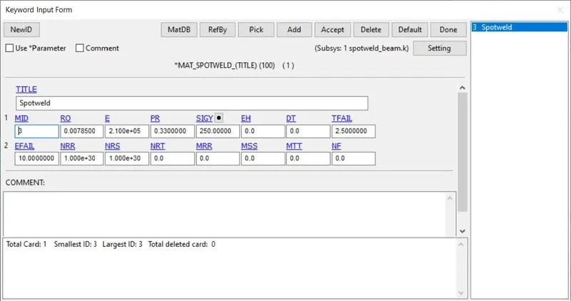
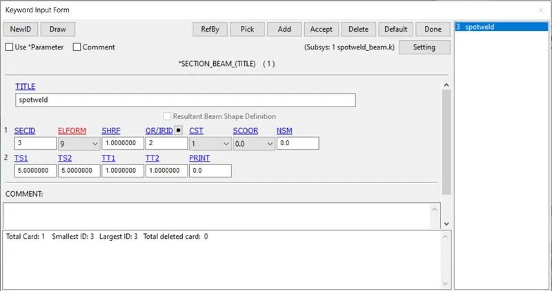
Assign *MAT_SPOTWELD_(100) material card withproperties of steel and Beam section card as shown.
3. Creating Contact:
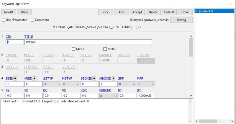
The contact between two brackets is defined using *CONTACT_AUTOMATIC_SINGLE_SURFACE by assigning the two bracket as slave as shown.
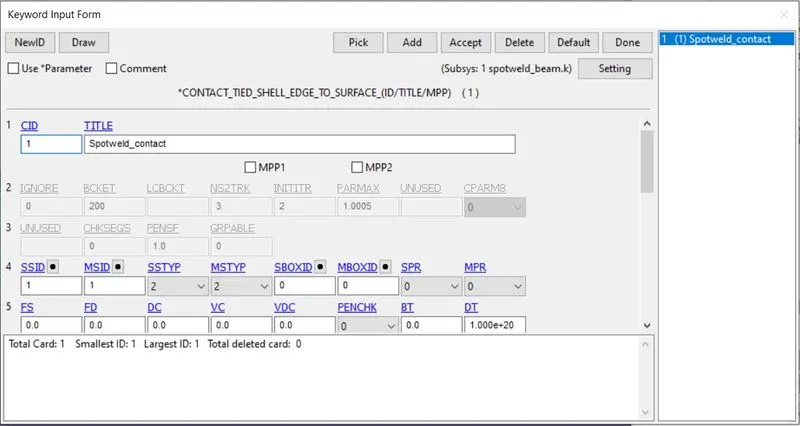
The Contact between Spotweld and the brackets is defined using CONTACT_TIED_SHELL_EDGE_TO_SURFACE where the beam elements are slave set and the brackets are master set as shown.
4. Creating Rigidwall:
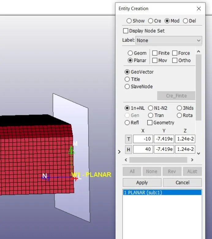
Rigidwall is created in order to simulate the crash. The wall is offset so some distance as shown.
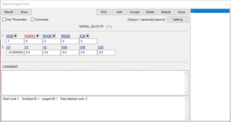
INITIAL_VELOCITY card with a velocity of 10 mm/ms in negative x direction is assigned to simulate the crash.
5. CONTROL_TERMINATION is assigned to terminate the simulation and output cards are assigned to get the output after running the simulation.
6. Creating Solid Element Spotwelds:
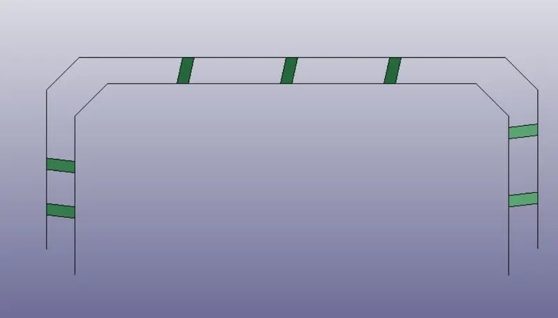
Spotwelds are created using Solid Hexa elements. To create beam elements go to Element Tools - Element Editing - Elem Type - Hexa and select the required nodes to create the spotwelds as shown.
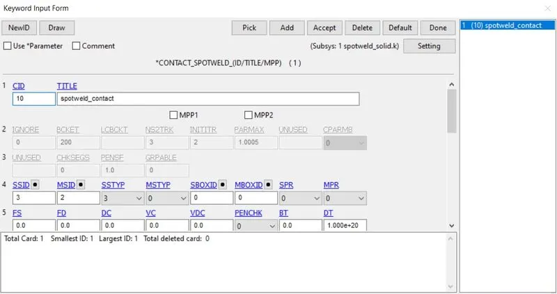
The Same deck setup done for beam element spotweld type is used and the section card is set for solid and the contact card is set to Spotweld as shown.
After running the solver the following outputs are obtained :
Von Mises Stress - Beam Elements
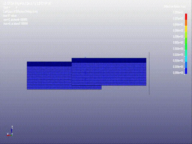
Von Mises Stress - Solid Elements
Axial Force - Beam Elements
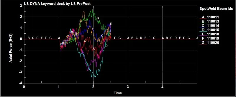
Axial Force - Beam Elements
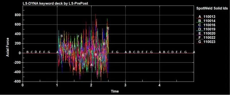
From the above graph it is evident that the beam elements go through large amount of tension (+ve axial force) and compression (-ve axial force) compared to Solid elements.
Shear Force - Solid Elements
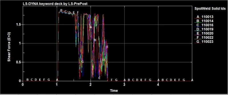
Shear Force - Beam Elements
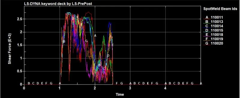
From the above plot the shear force on the beam elements is higher compared to Solid elements.
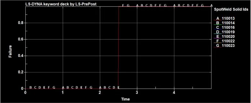
Failure - Solid Elements
Failuer - Beam Elements
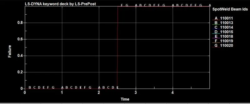
In both the cases the failure occures at the time 2.48
Conclusion:
The deck was set-up for beam and solid elements and simulation was run and the obtained results were compared using the plots.