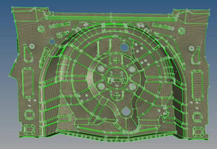
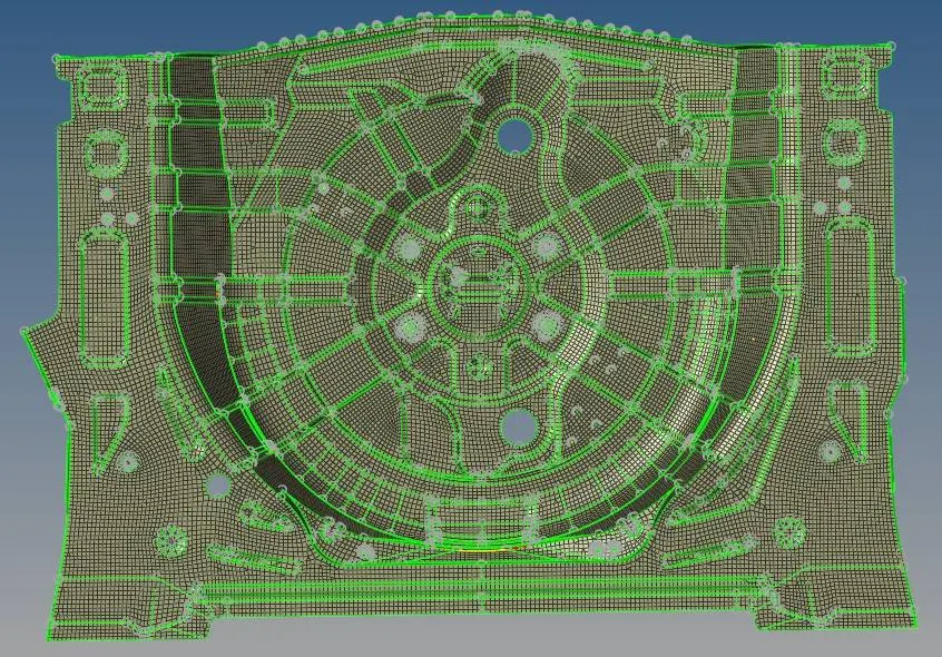
Manual mid-surface extraction of Back Wheel Panel with uniform thickness
Aim: To manually extract the midsurface of the given back wheel panel and to mesh the component as per the quality criteria.
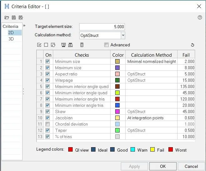
| S.No | Quality Criteria | Value |
| 1 | Aspect Ratio | 5 |
| 2 | Skewness | 45 |
| 3 | Warping | 15 |
| 4 | Taper | 0.5 |
| 5 | Min. Length | 2mm |
| 6 | Max. Length | 8mm |
| 7 | Min angle Quad | 45 |
| 8 | Max angle Quad | 135 |
| 9 | Min angle Tria | 20 |
| 10 | Max angle Tria | 120 |
| 10 | Tria % | 10 |
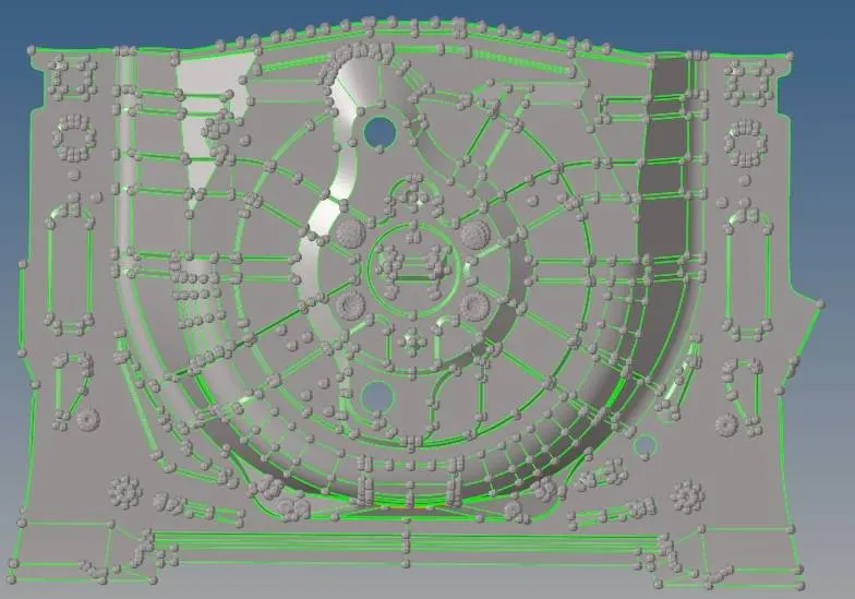
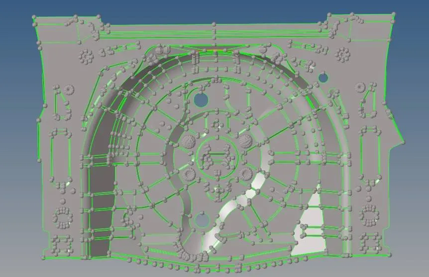
Model:
Procedure:
1. Measure the thickness of the component to extract the midsurface using Tools - Project - nodes option

Project the nodes by duplicating it on both surfaces and measure the thickness at different areas to check if the component has uniform thickness.
2. Extract the midsurface using Geom - Surface edit - offset - surfs option as shown.

Select all the surfaces and duplicate the surface - current component - reverse normal - offset to get the midsurface in one go as shown.
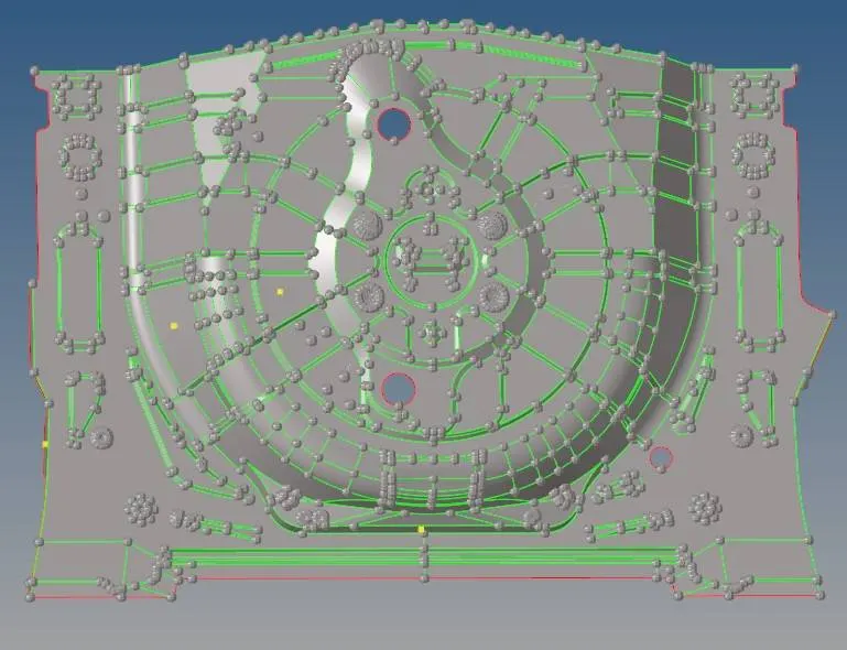
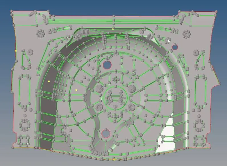
3. Check the geometry for missing surface and surface distrotion and perform geometry cleanup accordingly.
4. Go to 2D - automesh as shown.

enter the provided quality criteria in the criteria file settings as shown.
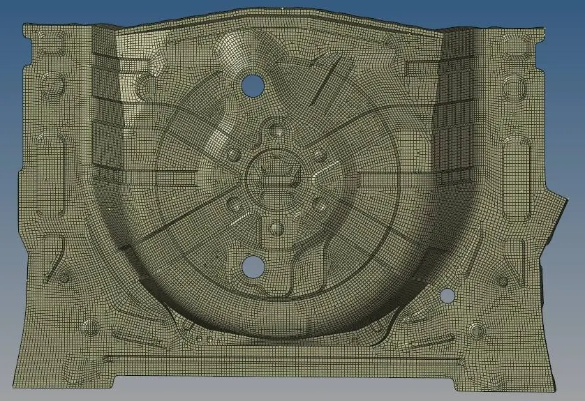
5. Mesh the component as per quality criterion and maintaining proper mesh flow as shown.
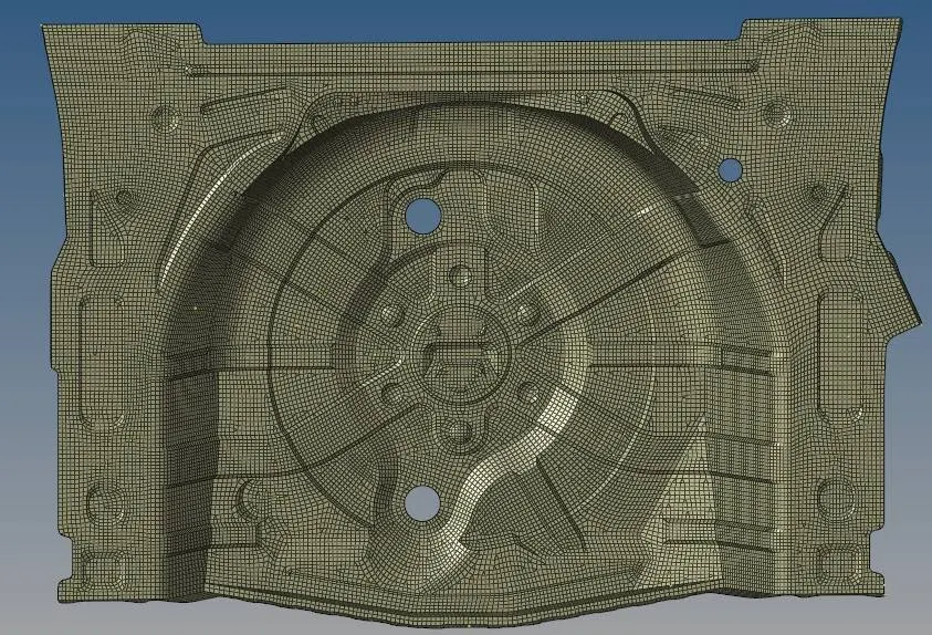
6. Check for free edges and check for quality. Fix the elements as per quality criterion.
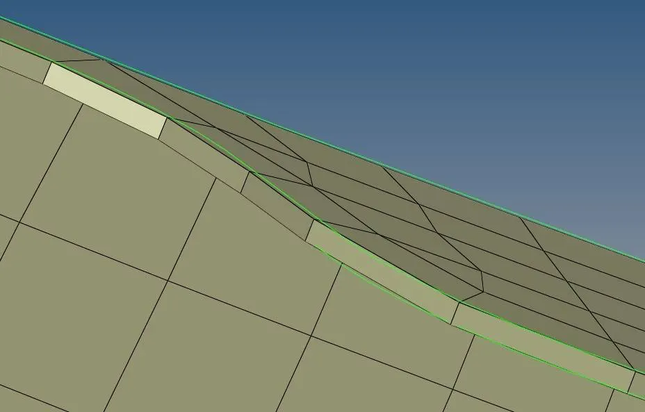
7. Assign material as steel in material card and thickness in the property card for the component.
8. Go to 2D dwtailed element representation to check if the assigned thickness is reflecting as shown.
Result:
Midsurface was extracted manually on the given back wheel panel and mesh was generated as per the quality criterion. Material Card and Property Cards were created and assigned to the component.